Month: November 2021

Sound Insulation Testing

Sound Insulation Testing

The Required Site Conditions for Sound Insulation Testing
During the sound insulation testing, our equipment produces high levels of noise; between 100-100dB. However, to record accurate test measurements, relatively quiet conditions are required on-site throughout the testing. Any site operatives working in the testing area will have to leave temporarily and any noisy works in the vicinity of the test areas including external site activity such as groundworks, drilling and banging will need to be halted. We also require full access to all the rooms being tested.

We provide a full testing schedule within our quotation which will clearly identify suitable couplings of test rooms that may require access to adjoining neighbours dwellings to enable us to complete the testing. APT Sound Testing will try to schedule the sound testing with you at a time when noise can be controlled to achieve the best possible testing results.

Sound Testing Services for New Build

How Long Will the Sound Testing Take?
The time taken to undertake sound testing varies from project to project as no site is exactly the same. Taking into account standard site conditions a set of tests on houses -two airborne walls will take one to two hours. A six-pack of tests on flats – 2 airborne walls, two airborne floors, and two impact tests will take between two to three hours. Throughout the sound testing, we will require full free uninterrupted access to the units/rooms in all test areas.

Should I inform my Neighbours of the Sound Testing?
Your neighbours will need to be contacted if access is required to their properties to complete the sound testing. Also as the sound levels produced during the test are very high it would be ‘neighbourly’ to inform the residents as they are likely to hear the test. If your project is a new build and/or a change of use and it’s built onto an existing property then chances are you will be required to undertake an airborne wall test.  We recommend that you check this with your local building control officer prior to the testing so you can plan access to the neighbouring properties accordingly.

Can I Observe the Sound Testing?
APT Sound Testing will happily give you a brief demonstration and overview of the test if so required; however, during the actual sound testing, we will need to follow stringent rules which restrict extra personnel within the test areas.

I want peace of mind that I’ll pass the sound testing
Poor Sound test results can occur for many reasons. The most common factor influencing acoustic performance is poor workmanship. Detailing is critical to maximising on-site acoustic performance, especially in floor and wall isolation and appropriate party wall and floor construction. If inadequate provision for the isolation of materials is not undertaken Noise flanking may occur which is another common reason for sound test failure.

We offer an acoustic design service to review the construction detailing. We also offer a sample testing service along with site inspections which provides a ‘one-stop acoustic solution’. We visit the site during the build process to check for any workmanship issues that may cause problems during the final pre-completion testing.

If you would like APT Sound Testing to review your site construction or to comment on their suitability, then please speak to us about our acoustic design advice service. This is a relatively inexpensive option that may avoid sound testing failures which result in expensive remedial treatment and delay your project handover.

For information in regards to sound testing or acoustic design, please follow our blog at: http://soundtestinguk.blogspot.co.uk/, or contact us on 0777 5623464 or visit our website at: www.aptsoundtesting.co.uk  

Sound Testing Explained

Sound Testing Explained

Sound Testing Explained

So what exactly is Sound Testing? Airborne and Impact Sound is transmitted through most walls and floors by setting the entire structure into vibration. This vibration generates new sound waves of reduced-intensity on the other side. The passage of sound into one room of a building from a source located in another room or outside the building is termed ”sound transmission”. 

Sound transmission loss or Sound Reduction Index, R dB, is a measure of the effectiveness of a wall, floor, door, or another barrier in restricting the passage of sound. The sound transmission loss varies with frequency and the loss is usually greater at higher frequencies. The unit of measure of sound transmission loss is the decibel (dB). The higher the transmission loss of a wall, the better it functions as a barrier to the passage of unwanted noise across the dividing (acoustic) partitions.

How to pass your Sound Testing in Bedford

Types of Sound Insulation in Buildings
Approved Document E stipulates that there are two types of sound insulation in buildings: airborne and impact. Airborne sound insulation is used when the sound produced directly into the air is insulated and it is determined by using the sound reduction index. Impact sound insulation is used for floating floors and it is determined by the sound pressure level in the adjacent room below.

A sound insulation test of a separating partition will be considered as a pass if the airborne sound insulation is equal to or greater than the DnT,w + Ctr value shown for the appropriate dwelling in the table, for airborne testing in new builds properties a figure of 45dB or greater is required and for Impact testing 62dB and below. For conversion properties a figure of 43dB or greater is required and for Impact testing 64dB and below.

What is DnT,w

DnT,w is an in-situ measured performance parameter that demonstrates the level of resistance to sound transmission between two adjacent spaces, such as flats or houses. The measurement will include both direct sound transmission and flanking sound transmission of the construction. Flanking transmission is the effect of sound travelling through the building and may be particularly evident where beams and joists bridge a common partition or along poorly isolated lightweight wall constructions.

The DnT,w of a separating wall or floor will typically be of the order 5 to 7 dB lower than the manufacturers specified Rw (single figure quantity of sound insulation) for the single element, due principally to the contribution from flanking sound transmission around the element when it is built on-site – this should always be accounted for in the initial acoustic design.

What is Ctr

Ctr is the spectrum adaption term. It is a correction attributed to the sound insulation quantity to account for urban traffic noise.

What is L’nT,w

L’nT,w is an in-situ measured performance parameter that demonstrates the level of resistance to impact sound transmission between floors. The impact measurement includes both direct sound transmission and flanking sound transmission.

Weighted Sound Reduction Index Rw

When specifying the acoustic performance of an acoustic partition in a more general manner, it can be useful to describe the sound insulation by a single number. The weighted sound reduction index, Rw , is a rating method given in EN ISO 717-1. This standard fits a standard reference curve to the measured sound reduction index curve.

Within the EN ISO 717-1 standard, a rating method is also given where the Rw value is completed by two C-terms which are applied to two models of the noise spectra for various types of noise. These two terms, Rw + C and Rw + Ctr, also include the frequency range 100 – 3150 Hz but can be extended to 50 – 5000 Hz. As industrial and traffic noise often have high sound levels which are also below 100 Hz, it is recommended that the extended frequency area is used.

The summary value, Rw + C, gives the reduction value in dBA for a spectrum with a level which is equally high in all third-octave bands. This can be used for:

•             Highway road traffic travelling at speeds in excess of 80 km/h

•             Factories emitting mainly medium and high-frequency noise

•             Living activities (talking, music, radio, TV)

•             Railway traffic at medium and high speed

•             Jet aircraft at a short distance

The summary value Rw + Ctr also gives the reduction value in dBA, spectrum with low-frequency dominance such as:

•             Disco music

•             Urban road traffic

•             Railway traffic at low speeds

•             Factories emitting mainly low and medium frequency noise

Both the impact and airborne insulation performance of floors and walls should be carefully considered from the start of the project to ensure that the minimum performance requirements for new and converted developments are met inline with Approved Document E

If you would like more information in regards to our sound testing and/or noise survey services, please contact us now on 01525 303 905or email us direct at info@aptsoundtesting.co.uk.

Sound Testing for New Build

Sound Testing for New Build

Sound Testing for New Build Dwellings
Sound Insulation Testing became mandatory in England & Wales in 2003, when Approved Document E was updated. Approved Document E requires new and converted to achieve a reasonable level of sound insulation between dwellings. The simplest way to comply with the requirements of Approved Document E; is to have on-site pre-completion sound insulation tests carried out on your project. We carry out full sound testing services in compliance with Approved Document E.

In our experience there is usually a level of apprehension with our clients having to undertake pre-completion sound insulation tests.  This is often down to the fear of failure. It should be remembered; however, that if the acoustic design specification is closely followed, and a good standard of onsite workmanship is maintained there is very little chance of failure.

Sound Testing Services for New Build


Sound Testing New Build

Approved Document E requires a minimum of one ‘set’ of tests for every ten units in each group and/or sub group.  Is usually broken down to the following: two airborne wall, two airborne floor and two impact sound tests. For example, if you have a block of 100 flats, all of the same construction, you would usually conduct 10 ‘sets’ of tests. If you have a development of 25 houses, with five different sub-groups (5 units in each) then you would usually conduct 5 ‘sets’ of tests.  As previously stated a set of tests usually consists of two airborne tests of separating walls and two airborne tests and two impact tests on separating floors; however, if no separating floors are available, i.e. in semi-detached or terraced houses, one set of tests would consist of two airborne tests of separating walls only.

To test the airborne sound insulation properties of a floor or wall, a sound source which consists of an amplifier and loud speaker is set up on one side of the wall or floor partition that is to be tested. We then turn the setting to turn on Pink noise. Pink noise sounds like the static that can be heard on a radio that is off station or the old TV test card noise.

This type of noise is used because it is made up of a wall of sound that has a wide spectrum of frequencies. This provides an indication of sound insulation performance for a wide range of sounds that may be experienced within a dwelling from speech to a kettle boiling. The pink noise is measured in the room which contains the speaker or sound source using a Class 1 Norsonic sound level meter; thereafter the noise is measured on the other side of the wall or floor partition that is being tested. In layman’s terms the difference between these two levels is the amount of sound that is stopped by the sound insulating qualities if the wall or floor partition/s.

The result is then corrected and adjusted depending on the echo or reverberation time within the receiving room, and any background noise such as builders work noise etc. to give the airborne sound insulation result (DnT,w). The results of these tests are then compared to the performance criteria of Approved Document E – 45dB new build & 62dB for conversions) and a pass or fail sound test certificate is produced

Testing Impact Sound Insulation Performance
To test the impact sound insulation performance of a floor, a Norsonic tapping machine which consists of five small hammers that are dropped onto the floor to simulate foot fall, is placed on the floor. The resultant noise in the room below is measured with a Norsonic Class 1 sound level meter and the amount of noise that passes through the floor is the impact sound transmission level and is expressed as a single number. This result is then corrected and adjusted depending on the reverberation time of the rooms as well as any background noise to give the impact sound transmission result (LnT,w). The results of these tests are then compared to the performance criteria of Approved Document E – 62dB new build & 64dB conversions) and a pass or fail sound testing certificate is produced.

If pre-completion test results do not satisfy the performance criteria of Approved Document E, then our test engineer will attempt to determine the possible causes of failure. This may be to do with construction detailing around services or at junctions, or simply, poor acoustic design. Once the results have been finalised along with the associated graphs, our acoustician (with the aid of the information from the sound test engineer, we should be able to determine the specific cause of failure. Once a specific reason for failure has been determined, we can then advise the client on remedial actions that can be undertaken.

Contact APT Sound Testing
If you have a project that’s needs acoustic design advice or needs pre-completion sound testing then please contact us by visiting the  APT Sound Testing Website and we should be able to offer you an acoustic solution to help your project achieve practical completion.

The Secret to Successful Sound Testing

The Secret to Successful Sound Testing

The Secret to Successful Sound Testing
There are many considerations to achieving successful sound testing on your development. The main areas that need to be addressed are the dividing wall and flor construction.  When dealing with walls you normally just need to worry about airborne sound; however, with walls, it’s both airborne and impact sound which can be far more difficult to deal with.

The usual noise problems associated with airborne sound transmission are TV noise, music, and speech. This can be dealt with by applying ceiling treatments as well as mass and isolation to the building components. Impact sound (footfall) performance is increased by the use of resilience layers and isolation of components to prevent noise flanking through the partition.

Secret to Successful Sound Testing

Airborne Sound Testing
For airborne sound testing Building Regulation Part E requires you to achieve at least 45dB for new build properties and 43dB for conversion developments, this applies both to party walls and floors between properties. This level is the difference between the source level and the receiver level during sound testing. Therefore, if the source level in one flat is 110dB and the receiver level in the neighbouring flat is 55dB, the level difference (or sound reduction performance) is 55dB.

The measurement is corrected for several factors such as background noise, room characteristics and frequency weighting, giving the final sound insulation performance value of the tested partition. In this case the higher the number the better the sound insulation performance. The measurement is done by using a Class 1 Analyser and the associated equipment.

Impact Sound Testing
For impact sound testing Building Regulation, Part E requires you to achieve at least 62dB for new build properties and 64dB for conversion developments. Impact insulation performance only applies to party floors and is related to the effectiveness of the floor construction in absorbing shock such as footfall noise. The measurement is done by using a Norsonic tapping machine (as shown below). The machine has 5 weights that tapping in regular succession on the tested floor which emulates footfall noise. The noise levels are taken in the receiving room below, which are then measured and averaged for different tapper positions, which then gives the sound reduction rating of the floor. In this case the lower the figure, the better the performance.

Good Acoustic Design
To try and ensure you meet the standards stipulated within Building Regulations Part E, careful consideration should be shown to the acoustic design detailing from the stat of the project. offset. Tackling the acoustic design for both new build and conversion projects requires two different construction techniques and acoustic design detailing. With new build properties, you have a blank canvas in terms of the overall design whereas with conversions you usually need to work with the existing’ onsite’ construction which can be quite difficult.

We offer an acoustic design package, which contains the following elements:

a.            Sample Sound Testing – of the existing construction. This offers an accurate overview of the acoustic performance of the existing partitions which enables us to offer a targeted acoustic design using the sound insulation performance of the existing construction.

b.            Acoustic Design Review – a full design review of the proposed developments party walls and floors.

c.             Site Survey Visits – to let us view the existing site construction. This allows us to check for potential problematic construction such as the inclusion of lightweight blocks in the existing construction. It also lets us check that the installation teams are installing the acoustic materials as per the manufacturer’s guidelines.

d.            Final Precompletion Sound Testing in compliance with Building Regulations Part E.

Useful Acoustic Design Considerations

a.            Avoid the use of lightweight blocks in the inner envelope construction and/or stairwell construction etc. as sound will travel both vertically and horizontally from dwelling to dwelling.

b.            The use of resilient suspended ceilings will help improve the performance of the floor partition.

c.             Ensure all support steels/timbers are carefully boxed out where they travel from flat to flat vertically and horizontally.

d.            Use a high-quality resilient acoustic membrane on top of the floor to improve the impact performance of a floor.

e.            Ensure all penetrations are fully sealed where they terminate through floors and they are adequately boxed with acoustic quilt and two layers of plasterboard.

In our experience, the main 5 considerations when designing for separating walls and floors between dwellings are: If used together or in various combinations they will improve sound insulation properties over a wide range of frequencies. The main factors are:

a.            Mass

b.            Isolation

c.             Absorption

d.            Resilience

e.            Stiffness

If used together or in various combinations they will improve sound insulation properties over a wide range of frequencies and should achieve compliance with Building Regulations Part E.

Successful Sound Testing with APT
In our experience, if the acoustic design is taken into consideration from the offset of the project, then it usually results in compliance with Building Regulations Part E.  In Some cases, sound test failure can also be down to poor workmanship rather than the acoustic design that is why we offer a full‘4 step’ acoustic package. If you have a project that needs acoustic design advice or sound insulation testing, then please visit the APT Sound Testing website or phone us directly on 07775623464.

Infrared Inspections to Electrical Installations

Infrared Inspections to Electrical Installations

Infrared Inspections to Electrical Installations
Electrical Thermal imaging surveys detect abnormally high temperatures and are a non-disruptive way of inspecting electrical and mechanical installations.

It provides an extremely low impact fault diagnosis tool for electrical fault finding. It requires no contact being made with the components which means that the components can be checked in a live state with little danger to the user, there is no effect on the components or interruption in any processes the electrical system may be controlling, thus no downtime for server rooms and/or manufacturing plant etc.

Infrared Inspections to Electrical Installations

Electrical faults can lead to breakdowns and the potential for fire hazards. In both cases the losses due to downtime and repair costs can become hugely costly.

What can cause failure in electrical equipment?

  • The age of the equipment – gradual breakdown/wear and tear.
  • Loose connections
  • Overloading sockets in your workplace
  • Loose or corroded contacts
  • Load imbalances
  • Poor cable joints
  • Overloaded transformers

The most common electrical equipment that requires surveys are:

  • Switchgears and switchboards
  • Distribution boards and fuse boards
  • Transformers
  • Control panels
  • Busbar systems
  • High voltage systems
  • Batteries
  • UPS systems
  • Heating and ventilation panels
  • Motor and pumps
  • Generators

Why should you undertake a thermographic survey?

Electrical thermal imaging surveys help to identify hot spots in electrical systems that you might not be able to see with the naked eye and makes sure that they are running safely. Thermographic surveys are low impact to the work environment so there is no down time for you to be affected by.

What type of Buildings need a thermal imaging survey?

  1. Commercial Buildings
  2. Office Blocks
  3. Schools and Colleges
  4. Warehouses & Storage
  5. Data Centres
  6. Military Infrastructure
  7. Flats, Houses & Residential Tower Blocks
  8. Housing Stock (Councils & Property Managers)

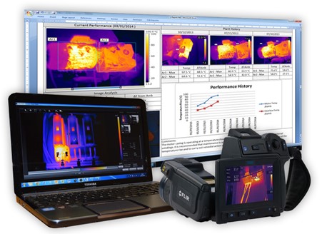
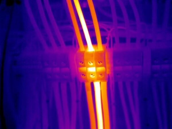
What does a Thermal image look like?

Based on infrared radiation, thermal images will have wide colour palate. The hottest areas of the thermal image from the thermographic survey will be yellow in colour, the coolest will appear in blue this provides a clearly defined imagine highlighting hot and cold spots.

Also, more expensive high resolution camera can be much more effective. The resolution of the camera is how many pixels the camera has on the scene. Higher resolution means that each image contains more information: more pixels, more detail, and a greater likelihood of getting an accurate measurement – that is why we always use cameras with a minimum of Resolution of 640×480 pixels along with Ultramax imaging for up to 1.2 MP thermal resolution. Here is some more information on why you should use high quality thermal imagining cameras.

Infrared Inspections to Electrical Installations

How often should Thermographic inspections be carried out?

It is recommended that thermographic inspections to the electrical installations are carried out during the formal periodic inspections, which are usually carried out annually. Thermographic surveys of critical parts for an installation could mean they have to be isolated in order for them to be inspected. This would obviously cause disruption; however, a routine thermographic inspection of these parts will help your business to run and could identify underlying defects which in turn could lead to a failure of the electrical supply. This shows how important it is to have thermographic inspections routinely incorporated into the annual maintenance schedules, to stay safe.

How many issues can I expect to find within my building?

Historically, we usually find defects during each visit. This can be loose or corroded contacts, load imbalances, poor cable joints or an overloaded transformer – all of which will generate excess heat and previous data from thermal imaging of electrical installations shows a significant rate of potential fault detection for an initial survey, typically in the region of one to two faults for every 10 panels inspected – if you have 50 panels that may result in 10 faults!

A thermal camera can often show the problem before an electrical test or visual inspection would uncover it. The severity of the problem can be determined by comparing the temperature rise of the fault with the properly operating component under the same loading conditions.

Past data from thermal imaging of electrical installations shows a significant rate of potential fault detection for an initial survey, typically in the region of one to two faults for every 10 panels inspected.

Thermal Imaging Inspection

How Much Does a Thermal Imaging Inspection Cost?

This one of the most common questions we get asked, and its has a simple answer: it depends on numerous factors.  When we sit down to work out our fee proposal for a Thermal imaging inspection, we ask the client a number of questions:

  1. The type and size of building.
  2. The amount of preparation required.
  3. The amount of time required to safely undertake the survey.
  4. The type of equipment required to undertake the inspection.
  5. The project location and subsequent travel costs/time.
  6. The required deliverables – what needs to be included within the thermal survey report.
  7. The amount of health and safety requirements i.e., some sites ask for 4-hour safety inductions.

We pride ourselves from being able to offer a basic electrical thermal survey from as little as £495 plus Vat, right up to the huge industrial areas that may need to be done in multiple visits that may be over £10,000 plus Vat and everything in between. It’s always best to call us to so we can get a more accurate overview of our project and quote; accordingly, so please contact us to discuss your project (along with any site-specific issues) and obtain a quote.

Are you engineers trained to carry out a thermographic inspection?

When you are employing a thermographer, you should check to see that they incorporate the high specifications possible for their inspections. Are they certified to Level 3 and do they use large format FLIR thermal imaging cameras?

Their specification should include:

  1. Level 3 thermographic certification
  2. Level 3 qualified thermographers
  3. Large format FLIR cameras with 45-degree lenses

The importance of clear and concise thermographic reports

We spend much a large amount of time on our thermography reportage, that’s why it’s one of the best in the industry, this is obviously a part of the service which is off site and clients don’t see. Whilst we may draw initial conclusions on site, which may need more investigation; usually, our final conclusions and report will only be finalised after all the data has been studied. It’s our ongoing aim to provide thermographic reports that are clear, concise, and easy to reference. Our aim is to take the guesswork out of the equation.

Please contact us now.

If you require a electrical thermal imaging inspection our professional and certified Level 3 Thermographer’s will carry out your thermographic Inspections for all necessary standards and current regulations.

All we need are a few details such as the building address and the number of electrical installations within the building. Floor plans and would also be helpful to allow us to orientate ourselves during the inspection. We will also send across our informative checklist to help you prepare for the thermal survey.

If you would like to contact us for more information on our thermal imaging services, please contact us on 01525 303905 or email us at info@aptsoundtesting.co.uk Please call 01543 225306 or fill out one of our contact forms to discuss our service levels and to run a thermographic inspection for your business. Talk to us today so we can keep you and your business safe.