Month: January 2023

What is an Electrical Thermal Imaging Survey?

What is an Electrical Thermal Imaging Survey?

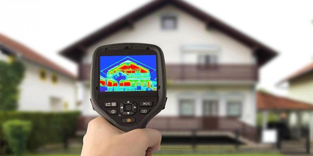
An Electrical thermal imaging survey is a non-evasive and non-destructive procedure using infrared technology.
Thermographic inspections are the only technique of work that is able to identify any electrical issues like the ones above, in a quick non-disruptive manor or to more precise safety standards. Not only is the thermal imaging fast and safe, it is also a great way to minimise costs as it allows defects to be detected before the equipment fails meaning you don’t need to pay out as much to get it fixed.

As infrared electrical inspections can spot faults before they occur, they can help to extend the life cycle of electrical equipment and identify energy savings for your industry. To try and help clients understand the what involved in a thermal imaging survey, please see our article: A Technical Explanation of Thermal Imaging Surveys.
Designing Buildings to Pass Sound Testing

What’s Involved in an Electrical Thermal Imaging Survey?
Thermal imaging is commonly used for inspections of electrical systems and components in all shapes and sizes. The use of thermography in any electrical installation can help identify faults before they occur, thereby preventing breakdowns, the need for replacement and even fires within the systems and buildings.

An electrical thermal imaging survey using a thermal imaging camera can be used on different types of equipment including:

• Busbar systems
• Distribution boards and fuse boards
• High voltage systems
• Transformers
• Control panels
• Batteries
• UPS systems
• Switchgears and switchboards


Using infrared technology on electrical infrastructure is a renowned method of predictive maintenance and done correctly it can be effective at fault finding prior to equipment failure but it needs to be carried out correctly. Our strict protocols ensure that the faults we document are indeed items that require investigation and possibly remedial work and not simply loaded circuits manifesting temperature.

Thermal imaging can help identify many potential failures such as:

• Poor Connections – Thermal imaging can detect the problems of a poor electrical connection early, the same goes for instances where the electrical cabinets may be overloaded.
• Electrical Leakage – Thermal imaging Surveys are able to find any evidence of a leak happening, in time for you to undertake remedial to preventing possible harm to you and damage to your building/s.
• Insulator Defects – Using thermography you can be protected from the dangerous parts of electricity, ensuring insulators are working properly.
• Internal Fuse Damage – Helps to prevent the risk of a fuse blowing, from an extensive current flowing through it.
• Oxidation of High Voltage Switches – thermography helps highlight potential resistance between connectors, enabling you to finding the problem before it occurs

Our Electrical Inspections involve:

• All panels removed where acceptable, safe to do so and on the Permit to Work
• All electrical equipment/panels/cubicles etc inspected have their own individual trend page which includes a thermogram and digital image, ambient, measured and delta T trending of temperature
• Trending compares data automatically between inspections. Last four thermograms are included on each page and all trend data is captured and displayed in a table and also in graphical format for Measured, Ambient and Delta T (meas/Amb) to allow for condition monitoring of equipment.

Detailed thermal imaging Fault Reports
Our detailed thrmal imaging reports contain fault pages that include a load correction formula is utilised during the inspection. Using component rating, actual load, measured temp and ambient temp, the following values are produced:
• Load corr temp: estimate of component temp if operating at 100% load
• Fault severity based on load corr temp – ref temp (from BS7671)
• Estimation of maximum amps to apply whilst keeping temperature beneath reference temp (BS7671)
• Instant report generation which can be emailed to the client at the end of the inspection

Why use a Level 3 Thermography Engineer on your electrical survey
The importance of using one of our Level 3 trained thermographers cannot be understated as they are trained to be write predictive maintenance and inspection practices and to develop test procedures and ascertain severity criteria. To try and help clients prepare for the thermal imaging survey to their building, we have written the following article: How we carry our thermal Surveys on commercial buildings.

To try and help facility managers with their electrical and mechanical surveys, we have also written the following article: thermal imaging inspections for facilities management. Also, throughout the UK BREEAM projects are becoming more common place.

BREEAM provides extra points to projects that have a BREEAM Thermal survey undertaken, as not many clients are aware of this, we have included more information in our article ‘What is a BREEAM thermal Imaging Survey’. Also to try and help clients prepare for their survey please download our Thermal Imaging Checklist.

APT Sound Testing use the latest high resolution thermal imaging cameras to undertake our Thermographic Surveys throughout London and the Southeast. Thermal imaging is one the quickest and easiest ways to undertake fault diagnosis on your buildings, as thermography can quickly and accurately identify building faults and a easy to follow report, so the defects can be quickly indented and rectified by the contractors.


We pride ourselves on offering a proactive service from start to finish. We have extensive experience of assessing thermal performance on many electrical systems on all types of buildings from commercial launderettes, right through to large power stations.


If you would like more information in regards to Thermography Surveys in London, please contact us now at: info@aptthermography.net or call us direct at: 01525 303 905
Sound Insulation Testing Terminology

Sound Insulation Testing Terminology

Sound Insulation Testing Terminology
Developers and landlords may need to improve sound insulation over a wide range of houses and flats. This may be due to the fact they have just built a new development that requires sound insulation testing under Part E or as part of a general refurbishment program, i.e. changing houses into flats.

Sound Insulation Testing

Describing Sound Insulation Testing

Often confusion can arise from the large amount of ‘terms’ used in conjunction with acoustic design and sound insulation testing. To help with this we have made a list of the following terms for clarity:

Absorption
This is the conversion of sound energy into heat, often by the use of a porous material.

Absorbent Material
This is a material that absorbs sound energy, such as acoustic mineral wool.

Airborne sound
This is sound which is propagated from a noise source through the medium of air. Examples of these are speech and sound from a television

Airborne Sound Transmission
This is direct transmission of airborne sound through walls or floors. When sound energy is created in a room, for instance by conversation, some of the energy is reflected or absorbed by room surfaces but some may set up vibrations in the walls and floor. Depending on both the amount of energy and the type of construction, this can result in sound being transmitted to adjacent parts of the building.

Air Path
This is a void in construction elements, which adversely affects the performance of sound resisting construction. Examples of air paths include incomplete mortar joints, porous building materials, gaps around pipes and shrinkage cracks – this can also effect the air tightness results.

Bonded resilient cover
This is a thin resilient floor covering normally of minimum 3-5mm thickness, which is bonded to the isolated screed surface to reduce impact sound transmission such as footfall noise, however it has a lesser effect when it comes to airborne noise.

Cavity stop
This is a proprietary product or material such as mineral wool (fibre) used to close the gap in a cavity wall.

Composite Resilient Batten
This is composed of a timber batten with a pre-bonded resilient material to provide isolation between the flooring surface layers and floor base.

Cradle/Saddle
This is an intermediate support system (with a resilient layer base, either pre-bonded or already integral) using levelling packer pieces to support a timber batten, isolating it from the floor base.

Decibel (dB)
This is the unit used for different acoustic quantities to indicate the level with respect to a reference level.

Density (kg/m3)
This is the mass per unit volume, expressed in kilograms per cubic metre (kg/m3). Blockwork is commonly referred to by industry in terms of strength (in Newtons). However, it is the density that has the important role in terms of sound insulation.

Direct transmission refers to the path of either airborne or impact sound through elements of construction.

DnT,w
This is the weighted standardized level difference. A single-number quantity (weighted) which characterises the airborne sound insulation between two rooms, in accordance with BS EN ISO 717-1:1997

Façade Testing
This Standard – ISO 140-5:1998) specifies the testing methods to evaluate the sound insulation in buildings and building elements for facades. Three rounds of a proficiency testing scheme for airborne sound insulation measurements have been performed according to the methods specified in the standard for a whole facade by using an external loudspeaker as the noise source.

Flanking element (flanking wall)
This is any building element that contributes to the airborne sound or impact transmission between rooms in a building which is not the direct separating element (i.e. not the separating wall or separating floor).

Flanking strip or edge strip
This is a resilient strip using foamed polyethylene normally 5 mm thick, which is located at the perimeter of a floor to isolate the floor boards from the walls and skirtings.

Flanking transmission
This is airborne or impact transmission between rooms that is transmitted via flanking elements and/or flanking elements in conjunction with the main separating elements. An example of a flanking element is the inner leaf of an external wall that connects to the separating ‘core’ of a wall or floor.

Flexible closer
This is a flexible cavity stop or cavity barrier which seals the air path in cavities linking adjoining dwellings.

Floating floor treatment (FFT)
This is a timber floating floor system which may use battens, cradles or platform base, all of which use a resilient layer to provide isolation from the base floor and adjacent wall elements.

Gypsum based plasterboard
This is a dry lining board applied to walls, ceilings and within floating floor treatments which has gypsum content. It may also have fibre reinforcement within the board.

Impact sound
This is sound which is propagated from a noise source through a direct medium. An example of this is footfall on a floor.

Impact sound transmission
This is sound which is spread from an impact noise source in direct contact with a building element.

Isolation
This is a strategy to limit the number and type of rigid connections between elements of construction.

L’nT,w
This is the weighted standardized impact sound pressure level. A single-number quantity (weighted) to characterise the impact sound insulation of floors, in accordance with BS EN ISO 717-2: 1997.

Mass
This is a physical quantity that expresses the amount of matter in a body. Walls and floors may be described in terms of the surface density (mass per unit area, kg/m2) of the wall face or the floor surface, which is the sum of the surface densities of each component of the construction. The density of materials is expressed as mass per unit volume, kg/m3, which can be provided via the core structure and linings such as in-situ concrete or solid dense block walls.

Mass per unit area (or surface density)
This is is expressed in terms of kilograms per square metre (kg/m2). This is often used to describe boards, panels, flooring and dry linings (see gypsum based board).

Resilience
This can reduce structural vibration transmission and still maintain material performance and overall dimensions, examples include floating floor treatments such as resilient battens or cradles, or resilient ceiling bars.

Resilient ceiling bars
This acoustic solution is generally metal based and vary in thickness from 11 mm to 30 mm. They are mounted perpendicular to the joist span direction and can increase both airborne and impact sound insulation. Care should be taken to ensure that the ceiling board fixings into the resilient bar do not come into contact with the joists and reduce the potential performance.

Resilient noggin
This is a small section of resilient ceiling bar which is used to assist in bracing non load bearing partitions.

Rw
This is a single-number quantity (weighted) which characterises the airborne sound insulation of a building element from measurements undertaken in a laboratory, in accordance with BS EN ISO 717-1: 1997

Sound Insulation Testing
Sound Insulation Testing is required near the end of a development to show that the performance of the party wall and floor partitions meet the standards as stipulated in Building Regulations Approved Document E. The testing methods for airborne and impact sound insulation is in full accordance with the suggested methods presented in BS EN ISO 140-parts 4 & 7: 1998.

Stiffness
This is can improve low frequency sound insulation, for example in floors, by reducing the potential for deflection or movement of the primary structure, therefore the correct spacing and depth of joists is important. If you have a project that requires acoustic design and/or sound insulation testing please let us know. APT Sound Testing will ensure you will have direct contact with the allocated acoustician from the start of the process, through to the successful completion of the sound insulation testing. 

If you would like more information in regards to acoustic services, please contact us at info@aptsoundtesting.co.uk, call 01525 303905 or visit our website at: www.aptsoundtesting.co.uk    

APT Sound Testing – Air Tightness Testing

APT Sound Testing – Air Tightness Testing

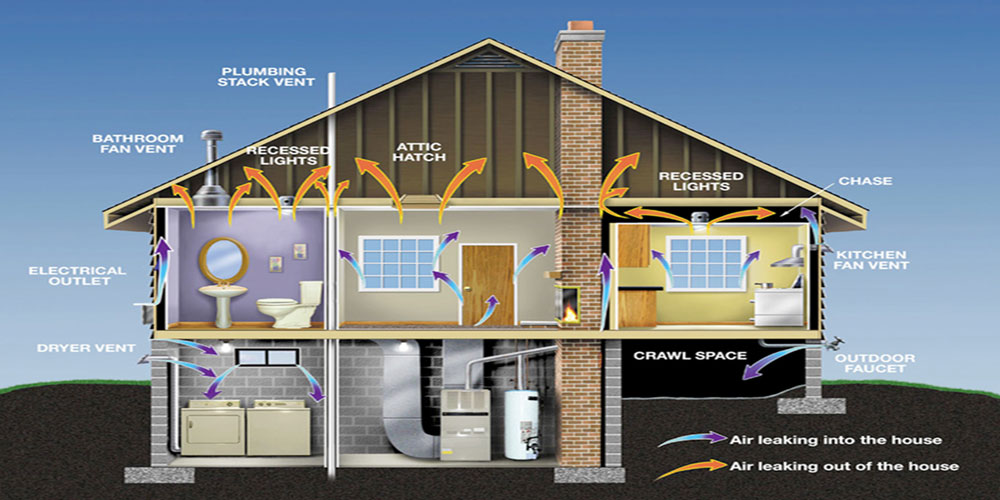
Air tightness testing, also known as blower door testing, is the process of measuring the amount of air leakage from a building through the building envelope. To try and help our clients better understand and prepare for their air tightness testing, we have tried to explain and answer our customer’s most common questions. For more information on our air tightness testing services you can also visit our Services Page.

What is Air Tightness Testing for Building Regulations?

Air testing is mandatory in the United Kingdom and is governed by Part L of the Building Regulations, this split into two parts; for domestic properties Part L1A should be used and for commercial properties Part L2A should be referenced.

Building Regulations Part L states air tightness testing should be carried to check the air leakage that occurs through a buildings envelope. The air leakage test checks the amount of air that escapes through gaps or air leakage paths through the building fabric. If the building is more air tight, less energy will be being needlessly lost, thus lowering the carbon emissions of the building. Air testing also shows how efficient a building is at retaining conditioned air which will also put less straight on your mechanical and ventilation system. Failing to maintain adequate air tightness can lead to up to 50% of heat loss from within a building to the outside atmosphere.

Air Tightness Testing

What air leakage target do I need to achieve?

Most new dwellings and commercial buildings need to achieve an air leakage of 3m3/hr/m2 to 5m3/hm2, this rate would usually be acceptable by building control and your SAP assessor as an acceptable result, although you need to check each your designed SAP assessment as there may be items within your buildings design that that may affect this figure.

How long does the air test take?

Most air tightness tests can be completed in 1-2 hours if they pass straight away; however, tests can take much longer if they initially fail. It usually speeds up the process if customs prepare their buildings in-line with our air tightness checklist as its means we can start the testing as soon as we arrive on site instead of waiting for the client to tape up areas, or make upgrades to the building envelope.  We also offer a smoke testing service to locate the air leakage paths within a building envelope which can also take extra time; however this often allows our clients to seal and pass their building at the first attempt even if their building initially fails the air test.

Air tightness testing

How do you undertake an air tightness test?

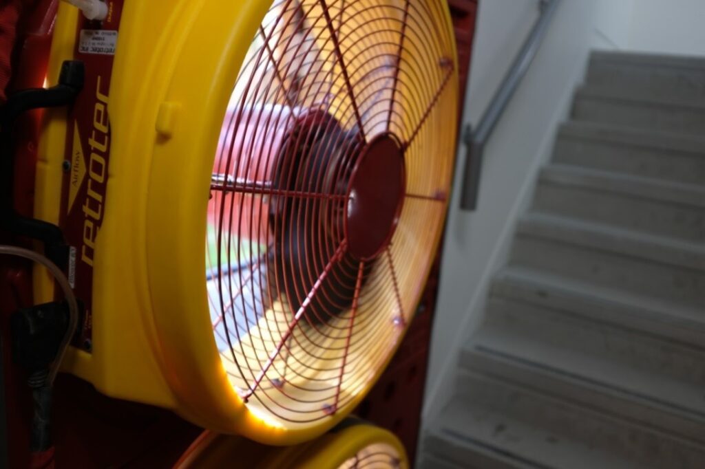
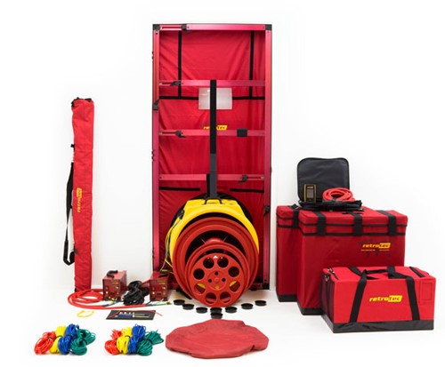
The air tightness test is undertaken in-line with Building Regulations Part L1 & L2 and ATTMA TS1 & TS2. Basically we measure the pressure differential across the envelope of the building by means of the temporarily installation of a large fan inside a door panel. Thereafter, a range of static pressures and environmental readings are taken. The fan is switched on and the air pressure in the property is gradually increased or decreased and the differential pressure is recorded at each step, usually from 25 Pa to 70 Pa. The total air flow required to achieve a pressure differential of 50 Pa is calculated and divided by the total building envelope area to provide the leakage rate in m3/h.m2@50Pa.

How do I prepare my building for the air test?

The more complete you’re building the more chance you have of passing the air tightness test at the first attempt. We send our and air test checklist with every quotation to help our client prepare for the testing. It is our aim to help clients pass their air test at the first attempt.

Basically you prepare the building in-line with our checklists and the items below, you will generally have a much better chance of passing the testing at the first attempt.

  1. The building envelope should be fully complete; this includes walls, floors and ceilings.
  2. All doors and windows must be fully fitted and able to shut tightly against their seals.
  3. All electric fittings must be installed and functional.
  4. All mechanical fittings must be installed and functional.
  5. Gaps within walls and floors must be sealed.
  6. All service penetrations must be fully sealed through the building envelope. 
  7. Bathrooms and kitchens must be fully fitted and all service penetrations sealed.
  8. All mechanical ventilation turned off with grilles sealed.
  9. All trickle vents to windows and doors must be sealed.
  10. All fireplaces must be sealed.
  11. Ensure water is present in soil pipes.
  12. 240v power must be available on site.

Whether you need air tightness test please contact us on 01525 303 905 or email us at info@aptsoundtesting.co.uk  to obtain a no obligation quote. If you need more information on how to prepare your building for the air test please download our air tightness testing checklist. 

Alternately, please call visit our website at www.aptsoundtesting.co.uk, for more information on our precompletion testing services

Sound Insulation Testing – Common Questions & Answers

Sound Insulation Testing – Common Questions & Answers

To try and help our clients better understand Sound Insulation Testing for Approved Documents E, we have collated the most common and questions (along with answers) clients have asked us over the last ten years. If you have further questions not contained within this article then please don’t hesitate to contact us.

What is Sound Insulation Testing?
Sound insulation is the property of a wall and /or dividing partition to resist the passage of noise. The sound Insulation testing is a method of quantifying the sound insulation performance of walls and/or floors. Sound Insulation testing can be carried out on party walls, party floors or facades of any building.

Sound Insulation Testing

Do I need sound insulation testing on my Property?
One of the largest single reasons for disputes between neighbours is noise complaints. Approved Document Part E – Resistance to the passage of sound describes minimum standards to be achieved by newly built domestic dwellings.

What is Approved Document E?

Approved Document Part E of the Building Regulations, sets out minimum standards for sound insulation performance to be achieved by party wall and party floors, you can achieve compliance with Part E by undertaking Pre-Completion Sound Testing

When is the Sound Testing carried out?
The Sound Insulation Testing is carried out when the buildings are complete. Windows should be in place with any vents closable. Internal and external doors should be in place, along with skirting, cornicing and plug sockets in place. Sound testing must be carried out before any soft coverings such as carpet have been laid to the floors. No furniture – such as beds or settees should be in the rooms during the sound testing as it will have an effect on the results. 

Are internal partitions within a single dwelling sound tested?
No, Laboratory test based performance standards (Rw) exist for certain internal walls and floors, but they are not intended to be verified as-built by on site measurement and therefore sound insulation testing is not a requirement; however, approved document E does state that internal partitions should achieve 40dB.

Do detached properties require sound testing for Part E of Building Regulations?
No, only attached properties require sound tests such as semi-detached dwellings or blocks of flats. Detached properties share no common partitions with any other properties.

How many sound insulation tests should I need on my Project?

Approved Document E states that one set of sound tests is required for every 10 units in a group or sub-group. A group or sub-group is defined where significant differences in construction or layout occur, for instance:

  • For a pair of semi-detached Houses – a set of tests would usually comprise two airborne sound insulation tests of a separating wall.
  • For Flats (up to 10 units) – a six pack would normally be required, this comprises of: two airborne wall tests, two airborne floor tests and two impact floor sound tests.
  • For Rooms for Residential Purposes (student accommodation, hotel rooms, care homes etc.) – a set of tests would usually comprise: one airborne sound insulation tests of a separating wall; one airborne sound insulation test of a separating floor; one impact sound transmission test of a separating floor.

Which plots selected for sound testing?
We usually specify the amount of sound insulation tests that is required on each project and this will be shown on a schedule within our fee proposal. This allows our clients to forward the schedule to building control to seek their approval prior to the test. We first look at the floor plans then work out a testing schedule taking into account testing through the projects ‘habitable rooms’ i.e. lounges & bedrooms where possible. When we have specified the sound testing schedule it should always be checked by building control and/or the client to seek their approval before the commencement of sound insulation testing.

How do I Prepare my Site for Sound Insulation Testing? 

APT Sound Testing always send out a sound testing checklist along with our fee proposals to help you prepare for the sound testing, as we always want our clients to be fully prepared so they can pass their sound testing at the first attempt.

How long will the sound testing take?

The time taken to undertake the sound insulation testing varies with site conditions, but generally a ‘6 pack’ set of tests on houses and flats takes about one to two hours. Obviously this depends on the site being fully prepared in line with our sound testing checklist.

Will the sound insulation testing disrupt work on site? 
we require relatively quiet conditions are needed to take accurate measurements. This means that anyone working in the testing area will have to leave temporarily and any noisy works in the vicinity of the test rooms will need to be halted i.e. using power tools or loud hammering etc.  

How do I know if I’m ready for a sound insulation test?
We send out a checklist with all quotations to allow our clients to check they are ready for the sound testing. Basically the plots should be at least at second fix stage – for further details please refer to our sound test checklist.

What sound testing equipment do you use?

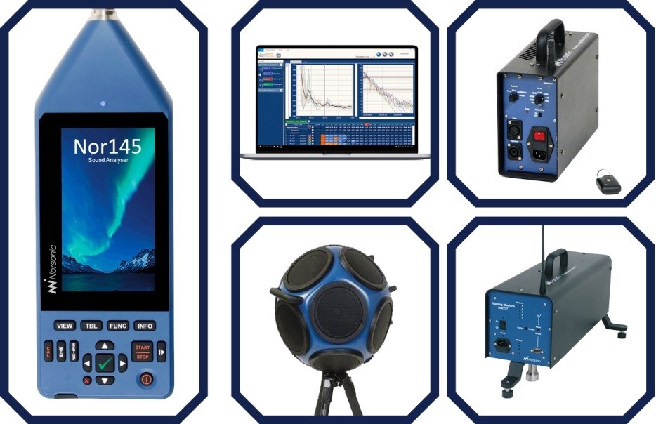
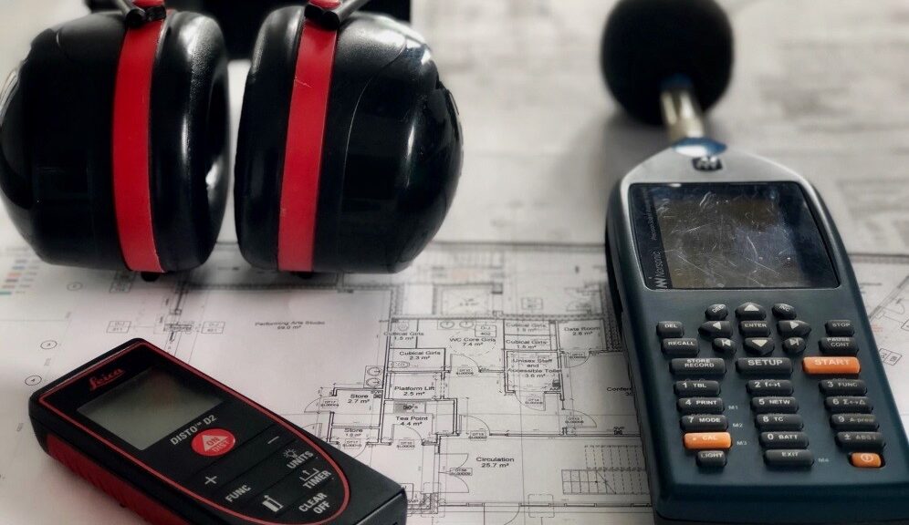
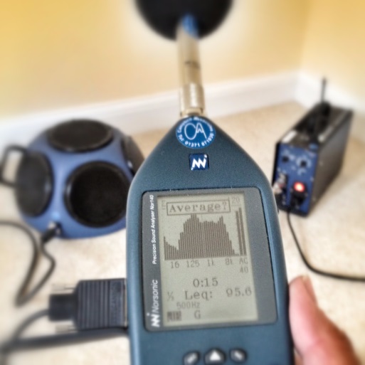
We use the latest UKAS calibrated acoustic equipment, for ease of use and reliability. unlike many other companies we able inform clients if they have passed or failed straightaway whilst on site. This allows us to offer acoustic advice and collect detailed construction information whilst on site, in the event of wall and/or floors failing the sound testing.

What if I only have 110V and not 240V on site?

Unfortunately we cannot undertake the testing off 110V or localised generator power; we will need 240V to undertake the sound testing.                   

Should I inform my neighbours of the impending sound testing?
If the building is attached in any way to occupied properties then you will need to inform the neighbours. We need to gain access to the neighbouring properties to undertake the sound test as we test the wall partition. You will also need to ensure that access is provided to the neighbouring properties throughout the sound testing.

Can you offer acoustic advice to help me to pass my sound testing?
APT offer an acoustic design service to help you design your buildings partitions to pass Part E sound testing. If you send through the relevant drawings such as sections and floor plans during the design stages of the project, we can check the design to see if there are any junctions or details where ‘noise flanking’ may occur, we can then advise if any changes are required to lower the chance of sound test failures.

Rest Assured

We believe in working with our clients on all types of projects from small end of terrace developments up to large blocks of flats. We believe that by being involved at the beginning of a project we can often save our clients expensive and difficult remedial works at the completion stage of a project.

If you need sound insulation testing for your current project, please call our team on 01525 303 905 or email info@aptsoundtesting.co.uk  We can provide you with expert advice and are happy to offer a free, no obligation quote along with our informative checklist to help you prepare for the sound testing.

Testing Air Quality for Volatile Organic Compounds (VOCs)

Testing Air Quality for Volatile Organic Compounds (VOCs)

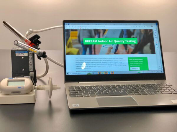
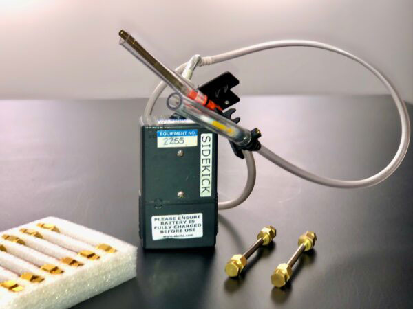
Volatile organic compounds (VOCs) are gases that are given off by many indoor sources. Concentrations of most volatile organic compounds are higher in indoor air than outdoor air and can lead to health concerns. That’s why indoor air quality testing for AOVs is very important.

What are VOCs and where do they come from?
Formaldehyde, is a very common VOC, it is a colourless gas with an acrid (sharp and bitter) smell. It is most common in building materials such as plywood, particleboard, and construction glues. Formaldehyde can also be found in curtains, drapes, and fabrics and in certain types of foam insulation, your lounge settees are one of the most common culprits.

Other sources of VOCs include the burning of fuels such as gas, oil, wood, coal, kerosene and tobacco products. Interestingly, VOCs can also come from personal care products such as hairspray, perfumes, cleaning agents, paints, lacquers, and varnishes.

VOCs can be much higher when a product is new and will usually be released from products during use and even in storage, that’s why indoor air quality testing is usually carried out to new and newly refurbished buildings prior to handover, which can also lead to extra BREEAM credits. However, the number of VOCs emitted from products tends to decrease as the product ages.

volatile organic compounds (VOCs)

What health concerns are associated with VOCs?
Volatile organic compounds (VOCs) include many chemicals that can cause shortness of breath, fatigue, headaches, nausea, dizziness and skin problems as well as eye, nose and throat irritation. Higher concentrations may be even more problematic causing irritation of the lungs, as well as damage to the liver, kidney, or central nervous system. Long-term exposure may also cause permanent damage to the liver, kidneys and/or central nervous system.

Some Volatile organic compounds are suspected of causing cancer to humans. The health effects caused by VOCs depend on the concentration and length of exposure to the chemicals, so minimising the VOC levels is critical in new and refurbished buildings. By undertaking VOC air quality testing, we can quickly establish the levels in your building and let you know if they are higher than what’s recommended.

Volatile Organic Compounds (VOCs)

The Indoor Air Quality Testing Experts
APT Sound Testing has a large amount of experience in the provision of BREEAM Indoor Air Quality Testing services. This ensures we are able to address all elements of Hea 02 ‘Indoor Air Quality. We have supported a wide range of BREEAM projects within the commercial and industrial sectors. These have included hospitals, health centres, laboratories.

Please get in touch with a member of our engineering team today at info@aptsoundtesting.co.uk or 01525 303905 to find out more about how we can help with the indoor air quality testing aspect of your BREEAM development or visit our case studies to review recently completed projects such as The Annexe (Imperial War Museum) and The Heals Building in Central London.