Author: admin

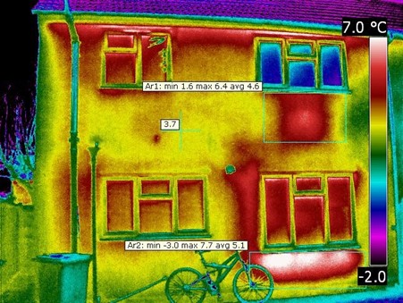
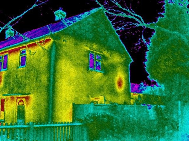
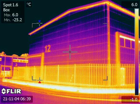
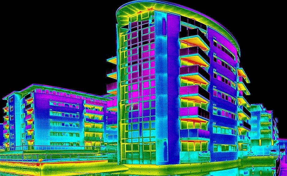
Is a Thermal Imaging Survey Worth Doing?

Is a Thermal Imaging Survey Worth Doing?

Is a Thermal Imaging Survey Worth Doing?

A healthy building envelope also makes the facility more comfortable and healthier for its occupants. This improved environment can also increase productivity and be very beneficial for the life cycle of a building.  A healthier building means healthier occupants – a double win for employers and employees.

What are other names for Thermal Imaging Surveys?

This procedure is also known as a thermographic survey, thermal survey, BREEAM Thermographic survey, BREEAM thermographic assessment, heat-loss survey, thermal imaging home inspection or Infrared thermography (IRT).

Thermal Imaging

How much does a London Thermal Imaging Survey cost?

This is one of our most common questions, with a very easy answer: it depends on various factors!

How much a thermal imaging survey costs depend on the following:

1.    The type and size of the building

2.    The number of buildings

3.    The preparation required

4.    Potential access issues that may slow down the survey

5.    The projected survey time and equipment required

6.    The location and travel costs/time

7.    The deliverable: in other words, the type of reportage is required.

Once the above items have been considered, we can forward an accurate fee proposal for the works.


When is the best time to do a Thermal Imaging Survey?

Thermal imaging surveys should generally be conducted in the early hours of a cold morning, approx. 2 hours before the sun rises to prevent solar loading on the building envelope. Generally, when it’s cold outside you heat the building to provide a temperature differential of 10c. The bigger and steadier the temperature differences between inside and outside, the easier the job will be. Also, thermal surveys should not usually be undertaken if heavy rainfall is present at the time of the thermal survey.

It is with noting that it is more difficult to conduct these types of heat loss survey during summer months as the ground temperatures and surrounding building envelope can maintain high temperatures for months on end; however, we can overcome this by using the latest advanced – and sensitive – thermal imaging cameras as well as utilising our highly trained and experienced thermography engineers. 

APT Sound Testing is a company that provides specialist thermal imaging surveys to customers through all industry sectors throughout the UK including construction and facility management projects throughout London and the South East.

Specialising in electrical thermal imaging surveys and building thermography, APT sound Testing is one of a few companies that only use surveyors that are trained certified to a minimum of ITC Level 2, which is the minimum requirement to undertake BREEAM Thermal Inspections throughout London and the rest of the UK for practicing thermographers.

We have over 15 years of experience carrying out building thermal imaging surveys in support of industrial and commercial applications, our thermal inspections reportage contains the required reporting structures to satisfy the requirements expected by Construction and Insurance Companies, Facility Managers, Building Controls and BREEAM 2011 Assessors etc.

Here at APT Sound Testing, we realise that thermal imaging inspections can be vital in establishing potential defects in your buildings at the earliest possible stage. This can save you time and money during future operations together with reducing the risk of making the wrong decision and potential building shutdowns.

The combination of highly trained and certified and experienced thermographic surveyors as well as high specification calibrated equipment guarantees our customers the best possible thermal imaging survey report to meet all of their needs.

Our thermal imaging team makes sure that customer satisfaction comes first, and our surveys are carried out with the utmost thoroughness and expertise.

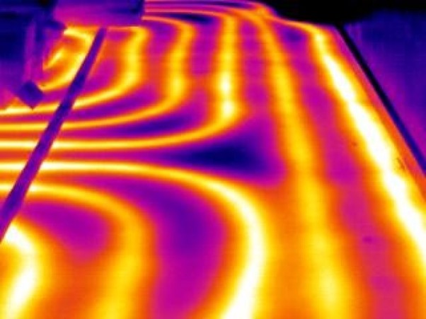
We have the equipment and experience necessary to identify underlying maintenance issues that can lead to expensive and unforeseen maintenance costs. Whether it BREEAM Thermal Imaging Survey be a Leak Detection Survey, an underfloor heating survey, a damp survey, or an energy efficiency survey, please contact us today and see how we can assist you.

To learn more about our London thermal imaging surveys and how they can help you maintain your home better, call APT Sound Testing today on 01525 303905 or visit the APT Sound Testing Services website.

Thermal Imaging for Electrical Equipment Maintenance

Thermal Imaging for Electrical Equipment Maintenance

Thermal Imaging Inspections for Electrical Equipment Maintenance

Over the last few years facility management companies are seeing the importance of electrical thermal imaging inspections for their predictive maintenance programmes.

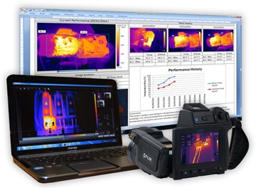
Thermal imaging is essential in electrical predictive maintenance programs because it identifies potential faults and allows for swift inspections and one image can show you various detail unlike using a spot pyrometer where you would have to test individual fuses, this allows maintenance teams to undertake remedial works before critical asset failure.

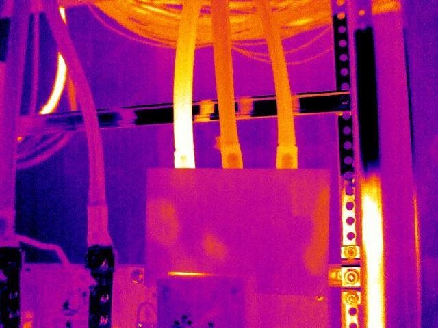
A picture containing an image from a electrical thermal imaging report.

At APT Thermal Imaging we can analyse your assets and provide you with unique easily understandable thermal imaging reports. That can be rolled out within your predictive maintenance programs. Also, also if you need help analysing the data provided within the thermal inspection report you will have your own dedicated thermographer at hand to explain everything in layman’s terms.

Electrical Maintenance thermography can be used on a wide range of electrical equipment including:

  • Distribution boards and fuse boards
  • Switchgears and switchboards
  • Control panels
  • Busbar systems
  • Transformers
  • High voltage systems
  • Batteries
  • UPS systems

It’s worth noting that our electrical thermal imaging surveys are carried out while plant and equipment is running. There will be no interruption to electrical supplies and your operations (critical assets) will not be affected while the thermal survey is being undertaken. Our thermal inspections engineers are all certified electrical professionals with extensive experience in thermal scanning of electrical systems.

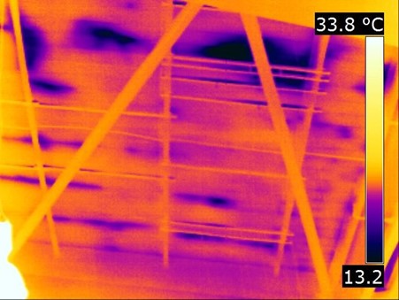
A picture containing a electrical thermal image.

Benefits of thermal imaging inspections

Thermal imaging inspections can help to prevent fires, explosions or breakdowns. It can find loose connections, overloaded and/or fatigued components, uneven voltage distribution and blockages in cooling tubes of transformers. The principal advantage over other types of testing and inspection is the ease with which components can be checked in a non-intrusive and safer way. Other benefits are normal operations can continue unabated with limited downtime and large installations with hundreds of electrical installations can be covered in a short space of time.

So why do you need electrical thermal imaging inspections.

It’s a very cost-effective way of ensuring that your electrical system doesn’t burn out or break down. This is especially important in industries with high voltage systems and/or where continuity of power is critical to the business, e.g. data centres, banks, utility suppliers, manufacturing, hospitals.

The most common benefits are:

  • Extension of equipment/building life
  • Less plant (critical asset) down time
  • Less energy wasted through inefficient operation.
  • The ability to prioritise and better target preventive maintenance
  • The avoidance of consequential damage to plant or facilities from fires/short circuits

Our clients include:

  • Office Blocks
  • Hospitals
  • Industrial Plants and facilities.
  • Warehouses & Cold Stores
  • Shops and stores

Thermal inspections of electrical systems must be carried out by suitably qualified personnel using the correct systems and procedures.

Why pick APT Thermography to undertake your electrical thermal imaging inspection?

All our thermal imaging engineers are trained to level 3, which is the highest level you can achieve as a thermographic engineer. We also use large format thermal imaging cameras; this provides you with the absolute best chance of solving any potential issues by utilising thermographic technology.

Our specification includes:

  • Level 3 thermographic certification
  • Level 3 qualified thermographers
  • Large format FLIR cameras with 45-degree lenses

As our level 3 certified electrical thermal imaging surveyors are trained to a minimum of Level 3 and use only the highest resolution thermal imaging equipment, its means we can keep further away from the danger zone. Our engineers also have a vast amount of experience in conducting this type of survey which further lowers risk.  We issue a risk assessment and method statement for each and every survey we undertake.

APT thermography has been carrying out professional thermal imaging surveys since 2010. We only use the highest resolution thermal imaging camera equipment, and our surveyors are all certified Thermographers with strong electrical, building and engineering backgrounds.

Our team of Level 2 & 3 certified professional Thermographers are highly experienced in carrying out thermal imaging surveys and have many years’ experience in all aspects of engineering, construction, maintenance, management, and professional survey work.

Our thermal imaging equipment is the best and most accurate on the market, ensuring we pick up faults that other equipment may miss. Our reports are professionally presented and are clear, concise, and easy to follow. We endeavour to give our clients a first class service every time.

Please contact us for more information

If you would like to contact us for more information on our thermal imaging services, please contact us on 01525 303905 or email us at info@aptsoundtesting.co.uk. Alternatively if you would like more information on how to prepare for your thermal imaging survey, please visit our website here or download our thermal imaging checklist
Sound Insulation in Historical Houses

Sound Insulation in Historical Houses

Improving the Sound Insulation Performance in Historical Houses
Heavy concrete floors and masonry walls, therefore, have very good sound insulation properties; whereas single met-sec walls with 1 layer of standard plasterboard on either side and lightweight timber walls are much poorer acoustically and usually fail the sound insulation tests. This isn’t the whole story as by isolating materials by utilising resilient fixings and/or layered systems, the better the insulation performance for absorbing impact sounds.

Many companies try to improve their sound testing results by improving wall thickness and weight of the material, however, simply adding layers of plasterboard to a standard wall system often has little impact to the sound test results. There is also the problem of covering important architectural internal features found in historic buildings, such as detailed cornices and other mouldings; therefore this is often a contentious issue, especially if it’s an upgrade to a listed building. 

Sound Insulation in Historical Houses

Read more on Cost-Effective Soundproofing for Walls

Installing baffles within airbricks and blocking up redundant chimney flues are often enough to greatly improve the sound test results, secondary measures such as the installation of draught-proof strips to doors and applying the acoustic sealant to the skirting’s boards at the wall/floor junction can also be beneficial and improve the acoustic levels.

To improve ambient noise levels it may be better to make acoustic upgrades to the front of the house where roads etc. are usually located. There is usually just a garden at the rear so this will usually be less noisy.

In all instances, acoustically the weakest part of external walls will be the window units. These are often Sash units and subsequently are one of the most important features within the external façade of historic buildings.

Many councils/local authorities will not let you remove and replace original window units unless the frames are rotten and beyond reasonable repair, however decent acoustic improvements can be made by installing a draught-proofing strip to the opening lights, and by providing an acoustic caulk seal around the window frame. If it’s extremely noisy a secondary glazing units along with demountable shutters may be an option. One of the simplest improvements can be made via the installation of good quality heavy curtains fixed close to the wall; this can also be one of the most attractive upgrades.

If the building is being subdivided into new apartments then the walls between apartments will need to be sound tested in line with Part E for Converted Dwellings. In this instance, we can undertake sample sound testing on walls and floors to check the existing sound insulation performance. Thereafter we can forward an acoustic design to comply with Part E of Building Regulations as well as undertaking the final pre-completion sound testing.

If you would like more information in regards to sound testing and acoustic design for your historical development, please contact us at info@aptsoundtesting.co.uk or phone us on 0777 5623464 or visit the APT Sound Testing website today.

Soundproofing Walls to Reduce Noise

Soundproofing Walls to Reduce Noise

Soundproofing Walls to Reduce Noise from Neighbours

Have you moved into a new house and realised you have noisy neighbours and thought it a good idea to soundproof your party walls?  

There are many soundproofing methods you can undertake to reduce noise through your party walls, many of which can be installed by yourself or by a trained handyman; such a hybrid acoustic panel plasterboard, which minimise the impact the build up, or lost space within the room; however, these types of solutions come at a price and are usually more expensive than a more standard ‘off the shelf’ solution.

Unfortunately, in most instances the more space you lose within the room/s typically the better the result. Although these come at a price and are usually more expensive than a more standard solution such as batten the walls, install 50mm of acoustic insulation (min 45/kg/m2) then install resilient bars to the timber baton. The wall can be finished with two layers of acoustic plasterboard with suitable laps. Although this type of system would be cheaper in terms of materials, it may cost more in terms of labour.

Soundproofing Walls to Reduce Noise

Another thing you need to check is where the noise is coming from – is it travelling through the centre of the wall, or the edges of the wall? If it’s the edges of the wall you may be experiencing a noise flanking problem which is quite common in older dwellings.

Also, you need to consider if it’s a brick/block cavity wall or a timber/metal construction as masonry walls usually have more mass which results in better airborne wall sound results.

One of the most common party wall soundproofing solutions would be to install a metal frame system that is independent of the wall – say a 75mm met-sec wall. This would need to be kept 20mm off the face of the existing wall. Then install a RW45 Acoustic Wool (min 45kg/m3) within the metal frame and finish with 2 layers of 15mm acoustic plaster board. However, this system comes at a space premium as will lose you about 115mm with skimmed 15mm sound board, or 125mm with two layers of 12.5mm soundboard

Soundproofing Walls to Reduce Noise from Neighbours

Here is a detail showing the types of some information There is some information on this type of system below, though you are going to lose approximately 100mm of room space when building an independent metal wall solution (min gap to the wall 20mm)

Also, it’s worth checking if you have a disused chimney breast in the house, as this can be solid between older properties and sometimes people connect their TV’s soundbars, speakers etc. to the chimney breast the base sound (lower frequencies) can travel through the solid construction. In this instance you can add baton, resilient bars, acoustic wool and soundboard to the chimney breast which should help.

Another issue may be joists which over-hang the cavity and touch the other joists or the wall in the neighbouring property which can quite a difficult to remedy. Also, on older houses they often used a “soldier course” of brick, the bricks were laid on end, hence the word “soldier” as opposed to being laid flat – to see if this is the case, you need to lift a couple of floorboards along the party wall and have good look at the pointing on the soldier or standard brickwork.

On closer inspection you’ll often find gaps in the masonry mortar, as the bricks are harder to lay properly due to the confined space between the joists.  Also, also the mortar may degrade and crumble due to the general movement in the timber joists (deflection) as well as shrinkage. In most cases the mortar can be replaced/repointed. In some cases, large areas of masonry may be missing which will need to be replaced. You can also install some extra acoustic wool within the joist voids against the party wall, which should further improve the soundproofing.

Soundproofing Walls to Reduce Noise from Neighbours

Have a look at the Gyplyner system below, it’s quite a robust and cost-effective solution as it reduces the build-up of an independent wall solution, whilst maintaining good soundproofing properties, this system would lose you about 52mm with skimmed 15mm sound board, or 62mm with two layers of 12.5mm soundboard. It’s a good off the shelf solution as the GL1 profile is held in stock by most large building merchants and the brackets a just screwed to the wall and bent round, then screwed to the GL1 profile, which makes it quite quick and easy to install.

Sometimes a single skin of lightweight blocks (such as thermalite) may have been used in the party wall construction which is a poor soundproof wall construction due to its lack of mass. This type of masonry may be only 500kg/m3 (50kg/m2), masonry should be around 1850kg/m3 (185kg/m2) which can easily lead to sound test failure if used in the inner envelope construction and or party walls.  

It’s worth remembering for sound to conduct through a wall, it has to actually move or vibrate the party wall ever so slightly. A heavy mass wall is always much harder to move than a lighter wall. It is very important to note that a heavy wall will still vibrate, just not as easily as the lighter one.

If you understand the above elements that make up party wall and floor design and construction, you’ll have a more educated eye for the acoustic design on your dwelling,  for instance, the  4 main elements of soundproofing construction are:

  1. Adding mass in your party walls
  2. Decoupling of materials within party walls
  3. Noise absorption within party walls
  4. Noise damping in party walls

In a nutshell soundproofing is the art of trying to prevent vibrations crossing party walls and floor partitions.

Getting the acoustic design right from the word go, is key, and APT Sound Testing can help in all areas of sound insulation design and sound testing. Please get in touch on info@aptsoundtesting.co.uk  to request a quote or call us on 07775623464 or 01525 303905 to discuss your development.

Please Note: although we take every care to ensure the information was correct at the time of publication. Any written guidance provided does not replace the user’s professional judgement. It is the responsibility of the duty-holder or person carrying out the work to ensure compliance with relevant building regulations or applicable technical standards.

Sound Proofing – Adding Mass to Walls

Sound Proofing – Adding Mass to Walls

Sound Proofing – Adding Mass to Walls

How exactly do soundproof a wall? Well, that’s a very common question. Let’s start with a basic understanding of the main 4 elements of soundproofing construction – they are:

  1. Adding mass
  2. Decoupling of materials
  3. Noise absorption
  4. Noise damping

If you understand the above elements that make up party wall design and construction, you’ll have a more educated eye on the acoustic design of your project. view your problem room. In a nutshell, we are trying to prevent vibrations from crossing the wall partition.

Hand holding ruler over plans for soundproofing party walls

When it comes to soundproofing walls and ceilings, we cannot understand the importance of adding mass. However simply adding mass is not often enough, you also need to consider two important factors:

  1. That of what type of material to use.
  2. where the material should be installed within the wall construction.

when adding mass to walls in buildings one the most common ways is to add cement board or soundboard. This adds mass and makes the walls as heavy and thick as possible. Adding mass to walls is one of the easiest ways to decrease sound vibration, although will not reduce deep bass sounds from being heard.

Another good reason for adding mass to any room is a good way to provide extra insulation, which in turn makes the room more energy-efficient and environmentally friendly.

How do I work out the required mass?

Working out the required mass for the wall to pass the sound insulation test can be quite difficult. For instance, the acoustic rating of a typical masonry wall increases from 45 dB to 50 dB when the thickness is increased from 100 mm (block laid on edge) to 215 mm (block laid flat).

This doubling of mass does not need to be achieved by doubling the thickness of a wall, as you can greatly increase the mass by opting for masonry that has a minimum mass of 1900kg/m3 or (190/m2) whereas many lightweight blocks such as thermalite are only 500kg/m3 (50kg/m2), which can easily lead to sound test failure if used in the wrong situation such as the inner envelope construction and or a single skin construction for party walls.

Acoustic design party walls

It’s worth remembering for sound to conduct through a wall, it has to actually move or vibrate the party wall ever so slightly. A heavy mass wall is always much harder to move than a lighter wall. It is very important to note that a heavy wall will still vibrate, just not as easy as the lighter one, with this in mind we then need to use the 2nd element of soundproofing design which is the Decoupling of materials – this is covered in our next article here.

Getting the soundproofing design right from the word go is key, and APT Sound Testing can help in all areas of sound insulation design and testing. Get in touch on info@aptsoundtesting.co.uk  to request a quote or call us on 01525 303905 to discuss your development.

What Types of Sound Testing Do I Need 

What Types of Sound Testing Do I Need 

What Types of Sound Testing Do I Need 

Sound Testing needs to be carried out between pairs of rooms separated by party walls or floors. In most cases, the rooms to be sound tested will be the two main habitable rooms – living rooms and bedrooms. All new build dwellings and conversions that were built after this 2004 are required to have 10% of each party wall/floor construction type to be tested.

The sound test procedure involves setting up a noise source in a room on one side of the party wall or floor and measuring the noise on both sides of the partition. The three types of Sound Tests usually required – depending on the project configuration) are:

Airborne Wall Tests

Airborne wall sound tests may be required between separate dwellings where a lounge and/or bedroom are positioned against the dividing wall partition. The sound tests are undertaken by using a sound source, amplifier and loudspeaker to generate a high noise level in one room (the source room). Noise measurements are then taken in both the source and receiver rooms using a prescribed number of source and microphone positions.

The background levels in the receiver room are measured and the reverberation time in the receiver room is also measured. From the results, the airborne sound insulation (DnT,w + Ctr) is calculated and compared to the requirements of Approved Document E.

Airborne Floor Tests

For vertically separated dwellings, airborne floor sound testing may be required, where a lounge and/or bedroom sit’s against the dividing floor partition above and/or below a ‘habitable’ room. The sound tests are undertaken by using a sound source, amplifier, and loudspeaker to generate a high noise level in one room (the source room). Noise measurements are then taken in both the source and receiver rooms using a prescribed number of source and microphone positions.

Impact Sound Tests

For vertically separated rooms, an Impact sound test may also be required. This sound test is undertaken using a “tapping machine”, (as above) which drops a series of weights onto the floor of the upper room. The noise level in the lower (receiver) room is measured for a prescribed number of source and microphone locations. The background levels in the receiver room are measured and the reverberation time in the receiver room is also measured. From the results, the impact sound insulation (L’nT,w) is calculated and compared to the requirements of Approved Document E.

Non-Residential Sound Testing

It is worth noting that sound insulation testing may also be required in non-residential buildings such as schools, hospitals, workplaces, whereas built performance needs to be demonstrated to ensure noise-sensitive areas (e.g. classrooms, wards, meeting rooms) are suitably insulated from noisier areas or to comply with BB93 & BREEAM requirements.

Sample Sound Testing

If you have an existing building that you are about to convert into flats etc. and need to establish the acoustic performance of the existing partitions, we can undertake sample sound testing on walls and floors to check the sound insulation performance. Thereafter we can forward a targeted acoustic design to comply with Part E of Building Regulations, as well as undertaking the final pre-completion sound testing.

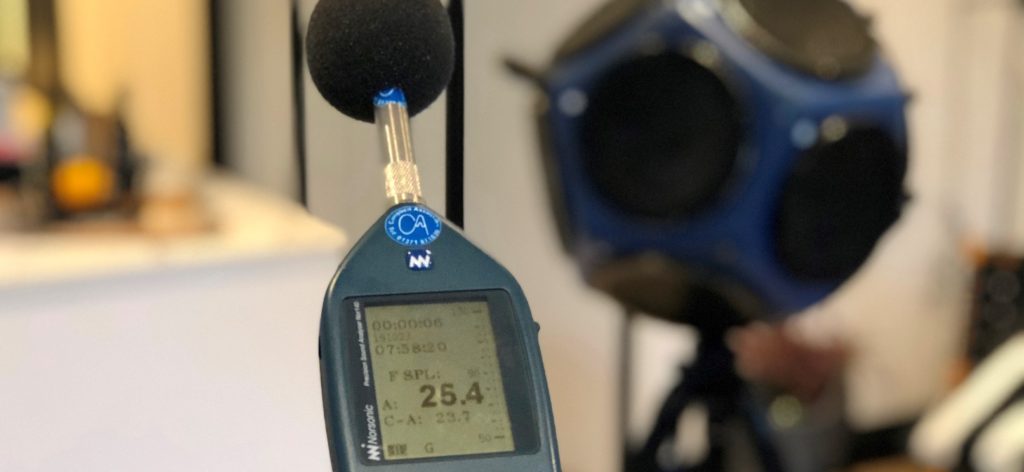
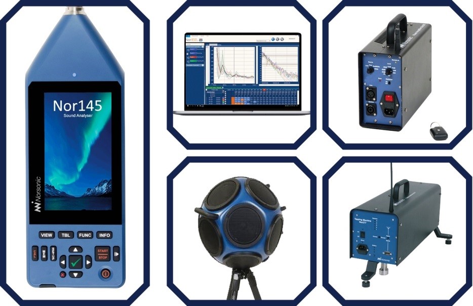
All APT’s test engineers carry the latest Norsonic equipment, which are class one rating all of our acoustic testing/sound testing is completed to a strict quality controlled standard. We provide full ISO & UKAS compliant sound testing.

If you would like more information in regards to your air and sound testing please contact us now at info@aptsoundtesting.co.uk or call us on 07775 623464

Designing Buildings to Pass Sound Testing

Designing Buildings to Pass Sound Testing

Designing Buildings to Pass Sound Testing
From the very start of the design phase of a new building, it’s extremely important that careful consideration is given to the acoustic element of the building.

By getting APT involved at the start of the design process we can undertake comprehensive acoustic design reviews and ongoing site surveys. We always advocate meeting with the design team at the earliest opportunity to go through all acoustic elements for the building’s design, taking into account the site constraints and the most cost-effective method of achieving Part E of Building Regulations. We try to forward any possible ‘onsite’ construction problems and difficulties in achieving successful acoustic construction and subsequently the sound testing for Part E.

Designing Buildings to Pass Sound Testing

Designing Buildings to Pass Sound Testing
Once we have completed the acoustic design review our services don’t finish there. We provide the site team with ongoing design support and site visits. You will have direct contact with the allocated acoustician from the start of the process through to the successful completion of the project.

Once the first phase of the building is completed, we can undertake sample sound testing to ensure the acoustic design and onsite construction methods are sufficient to pass Part E sound testing.

When it comes to refurbishment projects i.e. houses converted into flats and/or an office block into flats we can undertake a sample test of the existing wall and floor construction. Once we have established the sound levels for the existing construction we can then look at the extent of the acoustic upgrades to attain Part E Complaisance. This is much more effective than just forwarding an acoustic design that may be too excessive and expensive when the existing construction is already ‘acoustically’ robust and therefore only needs to improve by a few dB.

One problem we often encounter (without our design input) is that the building marginally fails during the sound test. The potential problem that is often overlooked is that many types of acoustic design/materials have attained an acoustic rating within a laboratory. It is very difficult and extremely unlikely that the sound levels achieved on a construction site will be as good as in the confines of a stringent laboratory environment.

When the construction assembly is tested in the lab, it is also certified and an exact description of the materials and the installation techniques are described in detail and followed to the letter, obviously, this should be replicated on your site as closely as possible, however, this seldom happens. This is one of the reasons why a 5dB point difference is allowed between the construction design on paper and the actual on-site construction performance. When you consider that sound doubles every 10dB, then 5dB can make a huge difference to the overall performance of the dividing partition under test. If consideration is not allowed during the design process then there will be a greater chance of a sound test failure on your project. 

Another potentially problematic area of sound transference and potential sound test failures is down to flanking sound. Noise flanking is when travels along a continuous path due to insufficient isolation/break within the building wall & floor elements. One of the most common flanking paths is along with the inner leaf of an external cavity wall. This may be due to lightweight block construction resulting insufficient mass to prevent noise transference.  

Unwanted noise travelling along flanking paths makes the building structure vibrate and this causes the sound to radiate into your room. One solution is to build another wall or ceiling in front of the original, but not connected to it (often called an independent wall or ceiling). APT can help to locate the flanking sound and propose a cost-effective design that will pass the sound testing and satisfy Part E of Building Regulations.

For the smaller projects, we undertake a more simplified acoustic design service consisting of a review of the design drawings, such as floor plans and sections. This usually takes place straight after planning has been approved as increased cost savings can be realised at the earliest stage. We can also undertake sample sound testing if the client is not sure of the existing onsite construction.

We can then evaluate the building design to ensure that it the walls and floors are capable of meeting the acoustic requirements of Approved Document E.

Some of the main areas we consider are:

•             There are no potential flanking points, where isolated partitions are wrongly mechanically fixed together to caused noise bridging or the wrong materials have been specified such as lightweight blocks etc.

•             The acoustic treatments for Soil Pipes, Stair Cases Steel Beams, etc. to ensure they are acoustically fit for purpose, as these are some of the many areas that get missed.

•             Acoustic floor treatments are compatible with the proposed floor finishes i.e. Carpets, Laminates, Floor Tiles and under-floor heating systems.

•             The Lighting specification to, ensure they are acoustically compliant to the overall design i.e. down lighter design etc.

If you would like more information in regards to sound testing please contact us on 01525 303 905, email us at: info@aptsoundtesting.co.uk or visit the APT Sound Testing website.

Pass Sound Testing in Conversion Projects

Pass Sound Testing in Conversion Projects

Robust Acoustic Design to Pass Sound Testing in Conversion Projects
It is essential that acoustic design is carefully thought out at the start of every conversion project to avoid sound test failures. Throughout the 1980s, most timber frame separating floors involved the following standard construction details:

  • Floorboards (18–22mm thick)
  • Gypsum-based board
  • Mineral wool batt (80kg/m3)
  • Sub decking
  • 220mm joists
  • 100mm quilt insulation between the joists
  • One/Two layers of gypsum-based board for the ceiling

Using the combination of floorboard, gypsum board, and mineral wool batt is termed a “platform floor”. There is a wide range of batt densities. If the density is too low the floor surface is able to ‘bounce’ and deflect much more easily. If the density is too high then the floor may be too hard and impact sound is able to transmit more easily to the residential dwelling below.

Pass Sound Testing in Conversion Projects

Sound Testing in Conversion Projects
Even when resilient battens are used, continuous structural contact along the joist between the floor sub-deck and ceiling provides a strong path for sound transmission. If contact between the ceiling and the joists can be reduced, an increase in airborne and impact performance will be achieved.

One solution is to add another ceiling element to the overall construction. This can provide the extra isolation required to pass the sound testing in London.  This can be achieved by incorporate resilient metal bars which are connected to the underside of the joists and mounted perpendicular (90˚) to the joist direction. If plasterboard has already been tacked to the underside of the joists you can firstly add timber batten and then add the resilient bars, also mounted perpendicular (90˚ to the batten.

Squeaking Floors
One common problem is that the Joists are often spaced too far apart can result in a reduction in floor stiffness and complaints about footstep noise at low frequencies. Over-notching of joists can also lead to a reduction in floor stiffness and also potential squeaking. This can result in successful airborne and impact sound tests, however, it won’t stop the squeaking of the floors under the extra load imposed by people walking above.

To help with impact sound testing, timber floors often pass as the separating floors normally have a resilient floor surface or “timber floating floor”. This not only assists impact sound insulation (against footstep noise transference) but also reduces airborne sound transference.

Timber floating floors must use a flanking strip to isolate the floorboards from the perimeter walls and skirtings. If flanking strips are not fitted then footstep noise can easily enter the structure via walls etc. and flank into the adjacent dwellings. In the 1980s, mineral wool was used as a flanking strip but it was difficult to turn round at the floorboard edge. It was also prone to deterioration due to compression and movement under dynamic load. As a direct result of this, 5–10mm polyethylene flanking strips were incorporated into the acoustic design and construction., They are also easier to install and do not degrade over time to the same extent.

There are many reasons why floors may fail the sound testing, such as the use of incorrect mechanical fixing can reduce the insulation performance provided by floating floor treatments and resilient ceiling bars. Using very long screws will lead to the bridging of the resilient layers and noise flanking. Inserting pipes or services within a platform floor can reduce the potential acoustic performance if they are not adequately boxed.  Placing pipes or cables under resilient battens can also bridge the resilient layer.

Potential problems with timber frame separating floors

  • Incorrect bridging of resilient layer by over-long screws/nails
  • Fixings connecting ceiling boards to resilient bars should not bridge to joists
  • Extra wide joist spacing that reduces floor stiffness
  • Platform floor resilient layers damaged by inserting pipes and services within the layers
  • Reduction in stiffness due to use of joist hangers
  • Ceiling boards not staggered
  • Over-notching of joists for services reduces floor stiffness
  • Incorrect omission of flanking strips at floor edge perimeters.

Whilst it is normal practice to have a building surveyed for its structural integrity, however often the acoustic conditions of a building are not considered until the project is well advanced and the partitions are already built.  In some cases, the acoustic performance of the building may not have been considered until the work is complete and the verifier requests a sound test to demonstrate compliance with the Building Standards. If it is found that the separating wall or floor does not comply you may need to action the following:

  • Extensive remedial works may be required to the wall/floor partitions.
  • The sound test completion certificate may not be accepted by the verifier
  • There may be considerable delays to entry for occupants and subsequent accommodation costs.
  • Pre-conversion sound tests can both avert the risk of non-compliance and avoid damage to the existing fabric.

Potential Problems with Services

It’s very common to run services such as electricity cables as well as water and gas pipes within the floor void. This is acceptable and should not require any additional acoustic attenuation measures. However, care should be taken to ensure that their installation does not damage the deafening material or resilient layers, which is a common cause of sound test failures.

It is strongly recommended not to run waste or rainwater pipes horizontally within a party floor. The pipes can then be boxed properly using insulation rapping and soundboard boxing.

Steel columns can be a source of flanking transmission, in particular hollow steel columns. They can also provide a strong path for structural impact transmission. Pre-conversion sound tests should be able to identify whether any columns act as a significant transmission path and whether any treatment is required. It may not be necessary to treat the column in all dwellings if flanking is limited, however, in many instances, the columns will need to be acoustically boxed to prevent sound test failure. One such treatment for columns would be to construct a free-standing metal stud partition around the column, incorporating 50mm insulation quilt and sheeted with two layers of gypsum-based board. Where columns pass through separating floors, as in old bonded warehouses, the junction between column and floor should be well sealed not only for sound insulation but also for fire. The column linings should be double lined with gypsum-based board (minimum mass per unit area 10kg/m2).

Timber beams do not significantly affect the sound insulation performance of a separating floor. However, if a beam has been installed for strengthening, the boxing around the beam may be a single sheet of lightweight board and may be fixed directly to the beam as this will result in a weak area for airborne sound insulation. This can be resolved by stripping off the boxing, packing any voids with dense mineral wool batt and re-sheeting with two layers of dense gypsum-based soundboard.

Contact APT Sound Testing
We hope the above information helps you to understand the potential problems with acoustic design and pre-completion sound testing on your development. If you have a project that needs acoustic design advice or sound testing in London, then please visit our Sound Testing website or phone us directly on 07775623464. 

The Different Types of Sound Testing

The Different Types of Sound Testing

The Different Types of Sound Testing
Sound Insulation Testing needs to be carried out between pairs of rooms separated by party walls or floors. In most cases, the rooms to be sound tested will be the two main habitable rooms – living rooms and bedrooms. The sound testing procedure involves setting up a noise source in a room on one side of the party wall or floor and measuring the noise on both sides of the partition.

Sound Testing for Part E of Building Regulations has been a mandatory requirement since July 2003. All new build dwellings and conversions that were built after this date require 10% of each party wall/floor construction type to be tested.

Different Types of Sound Testing

There are two mains types of sound tests that need to be carried out prior to the building handover, they are:

Airborne Sound Tests
Airborne sound tests are usually required between horizontally and vertically separated pairs of rooms. The sound tests are undertaken by using a sound source, amplifier, and loudspeaker to generate a high noise level in one room (the source room). Noise measurements are then taken in both the source and receiver rooms using a prescribed number of source and microphone positions. The background levels in the receiver room are measured and the reverberation time in the receiver room is also measured. From the results, the airborne sound insulation (DnT,w + Ctr) is calculated and compared to the requirements of Approved Document E. For new build projects, you are required to achieve 45dB for airborne sound testing through walls and floors and 62dB for Impact sound testing for floors. For refurbishment projects this changes to 43dB for airborne and 64dB for impact.

Impact Sound Tests
For vertically separated rooms, an Impact sound test may also be required. This sound test is undertaken using a “tapping machine”, (as above) which drops a series of weights onto the floor of the upper room. The noise level in the lower (receiver) room is measured for a prescribed number of source and microphone locations. The background levels in the receiver room are measured and the reverberation time in the receiver room is also measured. From the results, the impact sound insulation (L’nT,w) is calculated and compared to the requirements of Approved Document E.

Airborne Sound Testing of Building Facades
For the sound testing of external facades, we place the loudspeaker outside the building at a distance of 5m from the facade with the angle of sound incidence equal to  45° ± 5°  and such that the real traffic noise impact is simulated the best possible way.  The speaker and amplifier are used to generate a steady random noise signal via the loudspeaker source. The sound pressure levels are then measured at 2m in front of the facade plane and 1.5m above the ground.

All APT’s test engineers carry the latest Norsonic sound testing equipment, which is class one rating. All of our sound Testing is completed to a strict quality-controlled standard. We provide full ISO & UKAS compliant sound testing.

If you would like more information in regards to sound testing please contact us at 01525 303905 or visit the APT Sound Testing website today.

Floor Plenum Testing

Floor Plenum Testing

Looking at Floor Plenum Testing

A floor plenum is a void between a building’s floor structure and a raised access floor, used for distributing the conditioned air to the spaces above. It is important that conditioned air in a floor plenum flows into the occupied zone and does not leak into cavities, risers, stairwells, heating trenches or other adjacent zones. A properly sealed floor plenum will allow the diffusers and grilles to fulfil their primary role of delivering air at the correct flow rate.

APT Sound Testing undertakes floor plenum testing using a special fan that is set up in the test zone. All air ducts must be turned off and sealed. The test is conducted by taking a series of pressure readings. If the plenum fails the test we can then carry out a smoke survey to highlight the air leakage paths and issue a report for reference during the remedial sealing works.

If you require raised access floor testing, we can arrange a site visit and recommend the tests appropriate for your needs. We will advise you on the most suitable specifications for your structure and we will carry out extensive testing on your floor plenum.

If you want to know more about our plenum floor test services, please contact us today and our expert staff will be happy to advise you further.

In all instances, our strong focus on customer satisfaction, along with a can-do attitude, coupled with the knowledge of a UKAS accredited laboratory, are the key benefits to you when partnering with APT Sound Testing.

Floor Plenum Testing

What is a Floor Plenum?

A floor plenum is part of a building that normally facilitates air circulation for heating/air conditioning systems by providing pathways for either heated/conditioned or return airflows. The airflow is often supplied at a greater pressure than atmospheric pressure.

Air leakage from floor plenums can be a serious energy efficiency issue and a source of discomfort to users. A floor plenum is a void between a building’s floor structure and a raised access floor, used for distributing the conditioned air to the spaces above. It is important that conditioned air in a floor plenum flows into the occupied zone and does not leak into cavities, risers, stairwells, heating trenches, or other adjacent zones.

It is important that the air supplied to the floor plenum discharges through the floor-mounted diffusers or grilles rather than through joints in the raised access floor or between the raised access floor and the walls. A properly sealed floor plenum will allow the diffusers and grilles to fulfil their primary role of delivering air at the correct flow rate.

What is Floor Plenum Testing?

If you have floor or ceiling plenums in your building you need to be aware that a staggering 70-70% fail their first airtightness test. APT Sound Testing has years of experience of raised access floor plenum air pressure testing and can work with you to ensure you pass your floor plenum air test at the first attempt.

We can ensure that an onsite air test site audit is arranged as soon as the floor is in place; we can then undertake an initial floor plenum air test and smoke survey to check the air leakage result and check for air leakage paths within the plenum envelope. Once we have assessed the air leakage paths we can then supply a smoke survey report for your sealing contractors to use as a reference to ensure your plenums are adequately sealed

Why do so many floor plenums fail their first air test?

There are many reasons why 70-75% of floor plenums fail their first airtightness test. One of the most common reasons is due to a lack of understanding within the construction industry as to how airtight a plenum needs to be. One common problem is that many plenums are built and tested under laboratory conditions; unfortunately, there is a big gap between what happens in a lab to the reality of plenums construction on a building site. With multiple contractors needing to put pipes, cables etc. through the plenum, this is just one of many things that can affect the airtightness of a plenum. APT have years of experience and can work with you to ensure you achieve an air test pass on your plenum at the first attempt.

What happens if we fail the floor plenum test?

A large number of floor plenums fail the initial airtightness test so don’t panic. If we undertake the testing our UKAS accredited air tightness engineers will undertake a targeted smoke survey to highlight the main air leakage paths. We will then issue a smoke survey report for your contactors to reference during the remedial sealing works. We also allow for the option of visiting the site during the sealing works to ensure your contractors are adequately sealing the plenum prior to the second airtightness test. If you would like more information in regards to the most common air leakage paths, please visit our Floor Plenum Checklist.

The main considerations when constructing floor plenums?

In offices, carpet tiles are usually laid over the raised access floor, if joints between carpet tiles are not lined up with the joints between the raised access panel’s floor tiles or panels, the air leakage will be reduced, particularly if the carpet tiles are glued in place. That said, the laying of carpet tiles should not be relied on to achieve the target for the raised access floor itself as these can de-bond over time. 

Many raised access floors include electrical and date boxes. The air leakage of these boxes should be ascertained, to ensure that they will not significantly contribute to the raised access floor leakage, and reduce the air flor to the grills or diffusers. Where there are decorative or functional connections through the raised access floor, for example cabling to display boards, a suitable method of air sealing these penetrations should be designed.

The perimeter of the floor plenum where the access floor meets the wall is often an area of increased air leakage. To minimise this leakage it may be beneficial to fix a length of metal angle along the perimeter of the floor. Lengths of closed-cell board or neoprene strips will increase the quality of the seal between the raised floors and the wall and should prevent excess air leakage. 

The walls of floor plenums are most vulnerable to air leakage as they are dependent on the type and quality of construction. Plasterboard can be used as the airtightness barrier; however, care should be taken to ensure all joints should be sealed where boards abut other boards, walls, floors and the underside of the raised access floor. This is the same for coated mineral fire boards used in conjunction with fire mastic, the boards should be specified with an air leakage rate of 0.15 l/(s.m2)@50Pa with a life expectancy of at least 25 years.

While poured in-situ concrete floors don’t have any significant air leakage, hollow-core and solid composite precast planks need to be sealed along the plank joints and carefully sealed around service penetrations. Beam and block floors need to be covered by a screed to prevent excess air leakage

How we carry out Plenum Air Tests on your project?

In brief, a temporary tile is removed from the plenum and our fan housing is installed directly above the opening. A fan is then installed into the box and this is all sealed against the floor.

Any air handling ducts serving the test zone need to be turned off, isolated and temporarily sealed, stopping the passage of air to outside of the test zone via ductwork

Thereafter another tile is removed and a mock floor tile with a drill hole for the high-pressure tube is installed in its place.

After the equipment is set up a series of tests is undertake and the readings recorded and then checked against the floor plenum airtightness specification.

If the plenum test fails, your APT air test engineer will carry out a smoke test to look for air leakage paths.

Is there a Standard associated with Floor Plenums Tested?

At present, there is no set standard for floor plenum testing. The specification is usually set by the project’s Mechanical Engineers and is normally set in litres per second per square metre (l/s/m2). APT will need to know what pressure the specification is set at, e.g. 0.7l/s/m2 @ 50 Pascals. It is also possible that the specification can be set in l/s/m3 by the mechanical designers, for this type of test we would require the volume of the Plenum.

What are the most common air leakage paths within floor plenums?

In order to create an effective air-tight floor plenum, all utility penetrations and perimeter joints must be properly sealed. An evaluation of the following areas/components that can typically create inefficiencies should be undertaken during the early design phase and during the onsite construction. For clarity, we have shown the main air leakage paths below.

Floor Plenum Testing
  1. Penetrations through the access floor, walls and subfloor including
  2. Cable bundles and cable trays
  3. Pipes
  4. Fire/plenum barriers
  5. Cable trunking – must be internally sealed within the void
  6. Masonry work – incomplete or poorly jointed walls will result in greater air leakage
  7. Risers need to be properly sealed for plenums/ducting
  8. Plasterboard on studs at board edges and the ends below the raised floor level
  9. Gaps between compartment barriers, top of raised access floor and sub floor respectively
  10. Gaps between any curtain walling/glazing

If you are worried about the airtightness integrity of your floor plenum then please contact us now on 01525 303905. or get in touch via our contact form to discuss your specific requirements with our friendly and knowledgeable consultants!