Author: admin

Sound Testing Explained

Sound Testing Explained

Sound Testing Explained

Airborne and Impact Sound is transmitted through most walls and floors by setting the entire structure into vibration. This vibration generates new sound waves of reduced intensity on the other side. The passage of sound into one room of a building from a source located in another room or outside the building is termed ”sound transmission”. 

Sound transmission loss or Sound Reduction Index, R dB, is a measure of the effectiveness of a wall, floor, door or other barrier in restricting the passage of sound. The sound transmission loss varies with frequency and the loss is usually greater at higher frequencies. The unit of measure of sound transmission loss is the decibel (dB). The higher the transmission loss of a wall, the better it functions as a barrier to the passage of unwanted noise across the dividing (acoustic) partitions.

Approved Document E stipulates that there are two types of sound insulation in buildings: airborne and impact. Airborne sound insulation is used when sound produced directly into the air is insulated and it is determined by using the sound reduction index. Impact sound insulation is used for floating floors and it is determined by the sound pressure level in the adjacent room below.

A sound insulation test of a separating partition will be considered as a pass if the airborne sound insulation is equal to or greater than the DnT,w + Ctr value shown for the appropriate dwelling in the table, for airborne testing in new builds properties a figure of 45dB or greater is required and for Impact testing 62dB and below. For conversion properties a figure of 43dB or greater is required and for Impact testing 64dB and below.

What is DnT,w

DnT,w is an in-situ measured performance parameter which demonstrates the level of resistance to sound transmission between two adjacent spaces, such as flats or houses. The measurement will include both direct sound transmission and flanking sound transmission of the construction. Flanking transmission is the effect of sound travelling through the building and may be particularly evident where beams and joists bridge a common partition or along poorly isolated lightweight wall constructions.

The DnT,w of a separating wall or floor will typically be of the order 5 to 7 dB lower than the manufacturers specified Rw (single figure quantity of sound insulation) for the single element, due principally to the contribution from flanking sound transmission around the element when it is built on site – this should always be accounted for in the initial acoustic design.

What is Ctr

Ctr is the spectrum adaption term. It is a correction attributed to the sound insulation quantity to account for urban traffic noise.

What is L’nT,w

L’nT,w is an in-situ measured performance parameter which demonstrates the level of resistance to impact sound transmission between floors. The impact measurement includes both direct sound transmission and flanking sound transmission.

Weighted Sound Reduction Index Rw

When specifying the acoustic performance of an acoustic partition in a more general manner, it can be useful to describe the sound insulation by a single number. The weighted sound reduction index, Rw , is a rating method given in EN ISO 717-1. This standard fits a standard reference curve to the measured sound reduction index curve.

Within the EN ISO 717-1 standard, a rating method is also given where the Rw value is completed by two C-terms which are applied to two models of the noise spectra for various types of noise. These two terms, Rw + C and Rw + Ctr, also include the frequency range 100 – 3150 Hz but can be extended to 50 – 5000 Hz. As industrial and traffic noise often have high sound levels which are also below 100 Hz, it is recommended that the extended frequency area is used.

The summary value, Rw + C, gives the reduction value in dBA for a spectrum with a level which is equally high in all third-octave bands. This can be used for:

•             Highway road traffic travelling at speeds in excess of 80 km/h

•             Factories emitting mainly medium and high frequency noise

•             Living activities (talking, music, radio, TV)

•             Railway traffic at medium and high speed

•             Jet aircraft at a short distance

The summary value Rw + Ctr also gives the reduction value in dBA, spectrum with low-frequency dominance such as:

•             Disco music

•             Urban road traffic

•             Railway traffic at low speeds

•             Factories emitting mainly low and medium frequency noise

Both the impact and airborne insulation performance of floors and walls should be carefully considered from the start of the project to ensure that the minimum performance requirements for new and converted developments are met inline with Approved Document E

If you would like more information in regards to our sound testing and/or noise survey services, please contact us now by calling 01525 303905 or by visiting the APT Sound Testing Website today.

What is a BREEAM Thermal Imaging Survey?

What is a BREEAM Thermal Imaging Survey?

What is a BREEAM Thermal Imaging Survey?

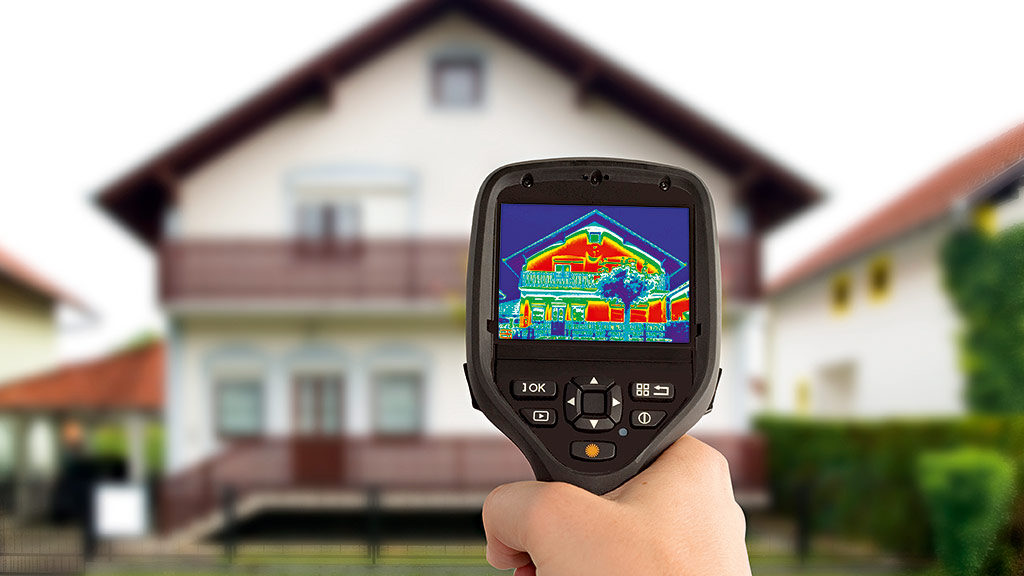
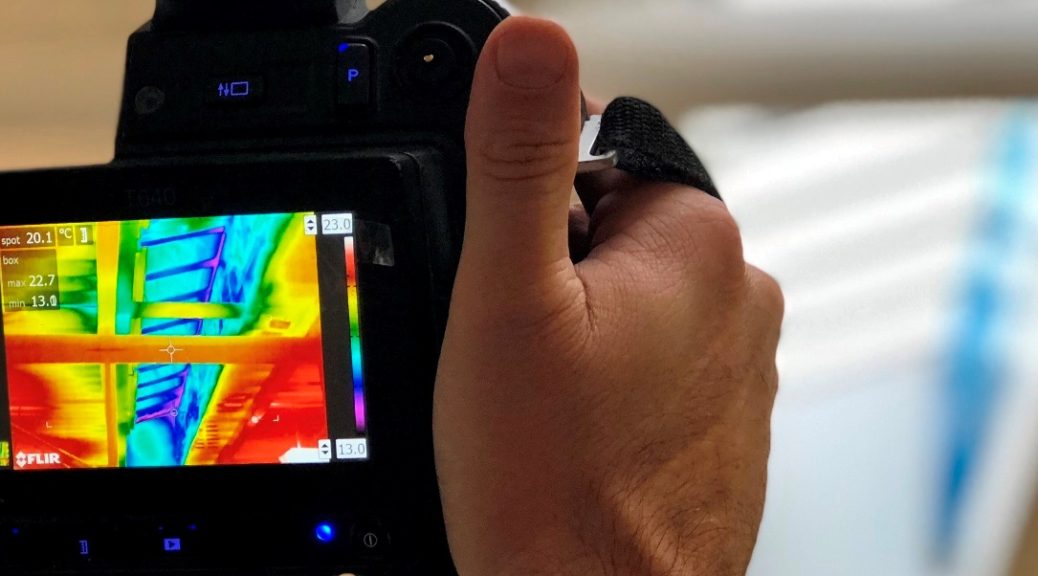
We often get asked this question; basically when Thermal imaging surveys are used properly, they can discover a multitude of issues including:

  • Areas of Thermal bridging
  • Missing or damaged insulation
  • Areas and pathways of heat loss
  • Areas of damp and mould growth

Thermal Imaging Surveys on buildings are one of the most effective ways to monitor sustainability performance. By Undertaking infrared surveys on new build commercial or dwellings, clients can be assured that their buildings are efficient with resources, ensuring effective thermal performance from every angle

BREEAM Thermal Imaging Survey

Thermal surveys can also identify potential improvements to reduce energy costs and CO2 emissions on existing buildings, thermography surveys can be used to assess the overall performance of the individual building fabric elements such that informed decisions can be made on improving energy efficiency. If required we can also undertake an in depth analysis, to estimate the potential cost and CO2 reductions if particular improvements are undertaken.

BREEAM Thermal Imaging Requirements

APT Sound Testing thermal imaging surveys are in accordance with the requirements set out in BS EN 13187. These requirements satisfy the BRE SD5076 standard for BREEAM credit, and a part of the survey you will need to allow for:

  1. Adequate Temperature Difference

To help to ‘see’ heat loss using a thermal imaging camera, a 10ºC temperature difference between the inside and outside of a building must be achieved. If a building has no operational heating system, temporary heaters can be used as long as the temperature difference is achieved.

  • Building Surfaces Must Be Dry at the time of the Thermal Survey

Before the thermal survey can commence all building surfaces should be dry to ensure that moisture evaporation does not alter the results. For building materials such as brick and/or block, its recommended that surfaces have been dry for at least 24 hours.

  • Full Access to the Internal and External Envelope.

In order to effectively measure surface temperatures within a building, full access must be given to our thermal engineers in order to inspect outside walls and surfaces from the inside. In addition to this, obstructions such as furniture should be removed at least an hour before the start of a survey. This is to allow local temperature conditions to stabilise before the test commences.

  • Avoiding Solar Radiation

To avoid the effects of solar radiation, thermal imaging building surveys should be conducted at least 2 hours after sunset or 2 hours before sunrise. This is important, as it means that thermal imaging surveys can be undertaken between 12pm – 3am during the summer months and 20:00pm – 6am during the winter months.

  • Avoid High Winds

Thermal imaging surveys should be undertaken when winds do not exceed 5 metres a second (18kph). This is to stop the cooling effect from wind which may affect the accuracy of the camera readings.

A BREEAM thermal imaging survey will also demonstrate compliance with the construction specification on newly constructed buildings in-line with Building Regulations Part L and sustainability assessments such as BREEAM. A large number of Building Specifications are including a thermographic survey into the schedule of works as a means of quality assurance and to achieve the required sustainability rating.

Where anomalies are identified during the BREEAM Thermal Inspection, we can highlight the issues within our report and provide as much help as possible in identifying remedial work required to gain a credit for a BREEAM compliance thermographic survey.

BREEAM Thermal surveys are completely non-invasive and non-destructive meaning that the building suffers no mechanical or physical damage at all.

If you require a BREEAM Thermal survey our professional and certified Level 2 Thermographer’s will carry out your thermographic Inspections for BREEAM compliance in accordance with all necessary standards and current regulations, all we need are a few details such as floor plans and elevation drawings and the building location to provide a quotation. We will also send across our informative Thermal Survey Checklist to help you prepare for the thermal survey.

If you would like more information in regards to BREEAM Thermography Surveys, please contact us now at: info@aptsoundtesting.co.uk or call Darren direct on: 07775 623464.

Building Regulations Part L  and this link both offer lots of useful information in regards to Thermography Surveys. If you would like more information in regards to our Thermal Imaging Surveys, please contact us at: info@aptsoundtesting.co.uk or call Darren Direct on 07775623464.

Alternately, if you would like more information on how to prepare for your BREEAM Thermal Imaging Survey, please visit our website at www.aptsoundtesting.co.uk or Thermal Imaging Inspection Checklist and you can also reference our blog at: airpressuretesting.blogspot.com or our Thermal Imaging Knowledge Base Page which offers handy tips on how to prepare for your Thermal Imaging Survey.

What is an Air Tightness Test?

What is an Air Tightness Test?

What is an Air Tightness Test?
Air leakage (also known as air permeability or air infiltration) is the air tightness of a dwelling through uncontrolled means such as cracks and gaps in the building envelope – walls, floors and ceilings.

Any ventilation system installed within a building is classified as a source of controlled air flow and is therefore not considered as air leakage and so these areas can be temporarily sealed during the air tightness test.

Air leakage is often felt as unwanted draughts, which will lower internal temperatures and may cause discomfort to building occupants especially in cold and windy weather.

Air tightness testing is a method of measuring and quantifying the air leakage of a building. Building Regulations Part L1A relates to dwellings and Building Regulations Part L2 refers to commercial buildings.

What is an Air Tightness Test?

Within the documents Air Tightness Testing is referred to as Pressure Testing and is the method by which developers measure the air tightness of their residential and commercial developments. Air testing shows how well properties will retain heat and in turn reduce carbon emissions, making them more efficient and cheaper to maintain.

An Energy Performance Certificate (EPC) is another compulsory requirement under Part L1A of the Building Regulations for all newly built residential and commercial units and these can only be issued when the air pressure testing results are available, to include within the SAP Assessment and thereafter the EPC.

How does Air Tightness Testing work?

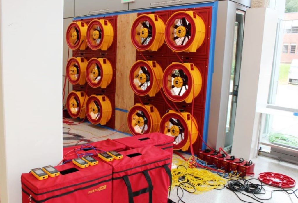
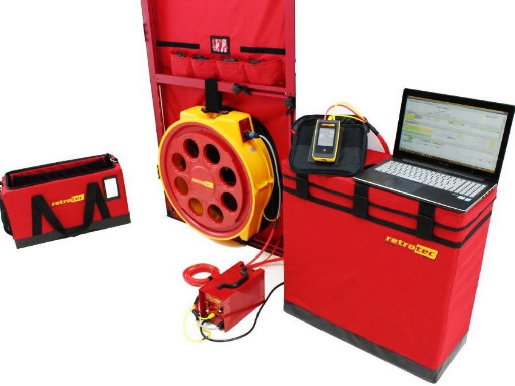
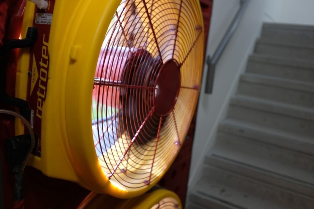
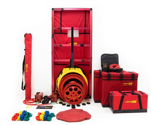
Air Tightness tests are carried out by increasing the air pressure within the dwelling/building and then measuring the rate by which the pressure returns to normal. This is carried out using large fan/s inserted in the entrance doorway. The number of units you will have to test will depend on the number of unit types on your development. For most dwellings a single fan will be sufficient to pressurise the building; however, for larger commercial units a multi fan system will be required which is usually set up in blocks of 3 fans to each doorway.

What Air Permeability Figure do I need to achieve?

The Design Air Permeability for the dwelling/building will be determined initially by the lead consultant or SAP/SBEM assessor. The maximum design air permeability allowable is 10 m3/(m2.hr) @50Pa; however, this the more common figure of 5 m3/(m2.hr) @50Pa is often used. By aiming for a reduced Design Air Permeability and improving levels of air tightness it will serve to further reduce carbon emissions and make the Target Emission Rate (TER) easier to achieve. It may also mitigate the cost of more expensive carbon emission reduction strategies.

There are many common areas of air leakage; or air leakage paths within dwellings and commercial buildings, they are: Behind Bath Panels, Kitchen and Utility Units, Intermediate Floors, Behind Skirting Boards, Boxed in Pipes & Soil Stacks, Fireplaces, Poorly Installed Trickle Vents, Windows and Doors, Recess Lights & Loft Hatches.

Special attention should be shown to the above areas throughout the construction process.

Another interesting fact is that UK studies have demonstrated that a house/flat with robust air tightness credentials can often attain a higher sale price due to reduced energy costs over the lifetime of the building.

Building Regulations Part L and ATMMA TS1 both offer lots of useful information in regards  to Air Tightness Testing, such as which plots should be selected and what parts of the building can be temporally sealed etc.   If you would like more information on how to prepare your building to pass an air tightness test then please download our air tightness checklist.

Please Contact us now

If you would like more information on our air tightness testing service, then please visit our website at www.aptsoundtesting.co.uk or contact us at: info@aptsoundtesting.co.uk. To have a chat about your project please call:  01525 303905

Improving your Air Test with Good Construction Detailing

Improving your Air Test with Good Construction Detailing

Improving your Air Test with Good Construction Detailing

Air Testing is the simplest and most popular method used in the construction industry to confirm compliance with Part L of the Building Regulations. The air test is simply a test of the building fabric integrity. Draughts and heat loss often occur wherever there is a hole or gap in the building envelope, resulting in the loss of heat/cooling which in turn will add to energy bills.

Since April 2006, air testing has been required to be tested for Air Permeability, in order to comply with Part L1 & L2 of the Building Regulations.  Since 2011 the air leakage target has reduced from 10m3/hr/m2 to 5m3/hr/m2. In the next 2 years it is expected that the target may be reduced to 3m3/hr/m2.

We provide a personal, helpful, efficient and cost effective air test service to our clients. Using the latest high power, portable door fans systems, we offer air testing to all building types, ranging from small rooms, flats & houses to office blocks & large distribution warehouses in accordance with the Building Regulations Part L1 & L2

Our air test fan systems are compact, discreet and fit simply into a personnel door. The system can easily be transported through areas of limited access or up to high level areas. Many contractors use us to undertake the testing in busy city centres or other tight access areas as we eliminate the site disruption caused by the larger trailer type air testing equipment.

In the event of a building failing an air test we then offer smoke testing – both hand-puffer for dwellings and large scale smoke testing for commercial buildings. This highlights the areas of air leakage through the building fabric. We can then undertake a full written and photographic survey as reference for your site management and relevant subcontractors. We will also offer FREE advice on the best method to seal any leaking areas. The main benefits of this are:

•             Air leakage paths are quickly identified in the event of a test failure

•             A full written air leakage report is forwarded so remedial works can start straight away

•             Building handover/practical completion and handover can be achieved more quickly
 

Construction Phase Consultancy

Air Pressure Testing has a practical ‘hands on’ approach during building construction and prefers to be involved as practically possible during this stage. We undertake periodic site visits to inspect the building envelope assembly as it is constructed and provide both written and photographic reports to enable any further works / remedial works deemed necessary to be accurately targeted. Site visits are generally to allow us to identify:

•             Insulation placement, continuity and effectiveness at thermal bridge junctions

•             Air barrier continuity within elements and at interfaces (particularly at sub-contract  package interfaces) 

Foundation/ground floor Initial works (Air Test risk factor 8)

a.            Ensure that any penetrations through the air barrier (e.g. service pipes) have been dressed. Pre- formed collars, sometimes referred to as ‘top hats’, which seal to the membrane and around the throat of the pipes are effective means of achieving a good airtightness seal.

b.            Ensure that the wall and floor damp-proof course/membrane forms an adequate airtight layer.

c.             With using timber frame construction, check that the sole plate is sealed to the foundation/floor-slab.

Internal Floors (Air Test risk factor 9)

a.            Using joist hangers can limit penetrations through the air barrier.

b.            If joists are to be supported by the wall, check that there is no air leakage into the cavity and the wall between the joists is fully filled/completed.

c.             Ensure timber floor sheets/boards are well fitted and sealed at their edges as well as at junctions with perimeter walls with mastic.

d.            Ensure the ceiling-to-wall joint has been sealed with mastic.

Eaves Level (Air Test risk factor 8)

a.            Ensure the airtightness layer between the wall and ceiling/roof is continuous ceiling below the roof space.

b.            Ensure there is a continuous air barrier over the whole ceiling area.

c.             Ensure all service penetrations (ventilation ducts from extract fans and light fittings) have been properly sealed where they penetrate the air barrier as this is a major air leakage path.

d.            Ensure all loft hatches are airtight and surrounds are sealed where they penetrate the air barrier.

External Doors & Windows (Air Test risk factor 7)

a.            Ensure you always specify good quality windows and doors.

b.            Always check that the wall-to-frame junction is properly sealed and continuous with mastic against the wall’s airtightness layer

c.             Ensure all windows and doors have an appropriate weather-seal between the opening unit and the frame – check for missing weather seals.

d.            All external doors should be fitted with draught excluders.

e.            Ensure the letterbox is fitted with a draught excluder.

Envelope Service penetrations (Air Test risk factor 10)

a.            Check for seals at service entry points (pipe and cable routes), e.g. around incoming water pipes,  gas pipes, electrical cabling, as well as waste water pipes for sinks, baths, washing machines,  dishwashers, etc. Seals should be provided internally and externally.

b.            Where multiple services penetrate at the same point, there should be sufficient space to fully seal round each of them.

Brick/block masonry construction (Air Test risk factor 7)

a.            Ensure the quality of construction as the work proceeds. Good mortar joints are required (i.e. no gaps around the blocks or bricks) on both internal and external faces – this also reduces sound transmission.

b.            Ensure all block-work is paint grade and painted were possible.

c.             The application of wet plastering, parging or the addition of fully-sealed dry lining will create a good air seal.

d.            Parging is an effective method of sealing around joists that penetrate the inner leaf of an external wall.

e.            Check that there is a good seal around all services that penetrate the masonry.

Plasterboard Dry lining (Air Test risk factor 10)

a.            Check the plasterboard is continuous (e.g. there are no large holes behind the kitchen units/bath). 

b.            Ensure that airtightness measures have been incorporated at all edges, particularly at the floor/ceiling junctions and around openings.

c.             Check the plasterboard is correctly detailed at joints, corners, reveals and window sills. Plasterboard should be mounted on ribbons of plaster or adhesive around all the edges (rather than dabs) to  prevent air leaking through the porous block-work behind.

Sealed Membranes & Vapour barriers (Air Test risk factor 9)

a.            Where the vapour barriers have been used as the air tight barrier, check that it is complete, that all joints have been sealed and it’s not damaged.

 Timber frame construction (Air Test risk factor 8)

a.            It’s usually easier to make timber frame dwelling airtight than other forms of construction. This is partly due to pre-fabricated construction and the use of the impermeable vapour barrier as the air barrier. The plasterboard layer can also become an air tight layer.

b.            Where vapour barriers have been used special care will be needed to avoid it being torn. Any damage to the vapour barrier must be carefully repaired.

Remedial Air Sealing Solution

1.            Smoke Investigation with Air Testing Fans:

APT’s Air Sealing Team utilise smoke investigation to identify the air leakage paths and prioritise which can be sealed first to attain an air test pass.

2.            Remedial Air Sealing Works:

APT can carry out the air sealing works. Typically allow for a 2-4 man Remedial Air Sealing Team. Adequate access must be provided for all sealing works. We provide all air sealing Materials – Rates provided on Request.

3.            On-going Air Tightness Assessments:

Enables the APT Sealing Team to seal the building until the fans indicate that the air

test would pass – thereby minimising the remedial works and time on site.

4.            Final Air Test:

APT’s Air Test Technician carries out a final independent test for compliance.

Whether you need a full on-going air tightness design/consultancy service, or just a simple air test, Air Pressure Testing have the knowledge and experience to ensure your building passes first time.

If you are unsure of the air tightness services you require, please visit our website – http://www.airpressuretesting.net/, call us on 07775 623464 or e-mail darren@airpressuretesting.net and one of our Air Tightness Consultants will guide you through the process, ensuring that you receive the right level of advice at the right time.

Air Tightness Tests for London Project

Air Tightness Tests for London Project

How Many Air Tightness Tests do I need on my London Project?

The air tightness test can be carried out on a selection of dwellings/ building types – three units of each type or 50% of that type, whichever is fewer. It many cases it is necessary to test all plots, otherwise a 2m3/hr/m2 penalty must be applied to all the plots on the site, this means that you will need to 3m3/hr/m2 if your SAP report stipulated a designed air permeability rate of 5m3/hr/m2. So to summarise the following testing will usually be required:

  • All new dwellings (based on a sampling rate)
  • All commercial new buildings other than dwellings
  • ‘Large’ extensions to buildings other than dwellings (if the footprint of the building extension is 25% of the original buildings floor area)
Air Tightness Tests for London Project

The dwelling(s) to be tested should be taken from the first completed batch of units of each dwelling type. For a dwelling to class as the same’ type’ as another it should consist of the following:

  • The same generic form, i.e. detached house, end of terraced, mid-terraced, semi-detached, ground floor flat, mid-floor flat, top floor flat, bungalow etc.
  • Have the same principle construction details
  • Have an envelope area that does not differ by more than 10%
  • Include the same number of storeys
  • Have the same Design Air Permeability (Air Pressure Test Target)
  • Have a similar adjacency to unheated spaces such as garages, unheated stairwells etc.
  • Have a similar number of apertures and penetrations, for example doors, windows etc.

To help builders and developers, there are two building standards that provide in depth information in regards to air tightness testing, they are Building Regulation Part L and ATTMA TS1 & ATTMA TS2

What is my Designed Air Permeability Target?  

Building Regulations Part L1A and L2A are specially aimed at new buildings and most are now required to have an air-tightness test. Part L1B and L2B cover work to existing buildings and do not generally have a requirement for air-tightness testing.

All new dwellings are required to have a SAP (Standard Assessment Procedure) calculation prior to building control approval. It is ultimately the SAP calculation that determines the air permeability target needed to be achieved and whether it is a requirement.

All new non-dwellings are required to have a SBEM (Simplified Building Energy Model) calculation prior to building control permeability targets and will require testing.

The design stage SAP and/or SBEM assessments provide the required ‘air permeability rate’ you need to achieve on the project. Clients often mistake the maximum permissible air permeability rate of 10m3/hr/m2 as their target; however it’s the ‘designed air permeability rate’ which you need to adhere to, which is usually much lower than this at around 3m3/hr/m2 to 5m3/hr/m2. If your project is in London, the requirements are often more stringent. Most air tightness tests in London need to achieve 3m3/hr/m2.

We are here to help you with your Air Tightness Test in London

If you are unsure how many London air tightness tests you require, please contact our friendly expert team for advice on helping properties achieve required emission rates for air testing. Simply the use our contact form on this page, or call our offices, to chat about your specific air testing requirements with our knowledgeable team of air tightness consultants.

APT Sound Testing can assist you through the process and help you determine the specific air tightness testing requirements for your project. If you require more information please visit our website at www.aptsoundtesting.co.uk

Different Types of Sound Testing

Different Types of Sound Testing

Different Types of Sound Testing
Sound Insulation Testing needs to be carried out between pairs of rooms separated by party walls or floors. In most cases the rooms to be sound tested will be the two main habitable rooms – living rooms and bedrooms. The sound testing procedure involves setting up a noise source in a room on one side of the party wall or floor and measuring the noise on both sides of the partition.

Sound Testing for Part E of Building Regulations has been a mandatory requirement since July 2003. All new build dwellings and conversions which were built after this date require 10% of each party wall/floor construction type to be tested.

There are two mains types of sound tests that need to be carried out prior to the building handover, they are:

Airborne Sound Tests
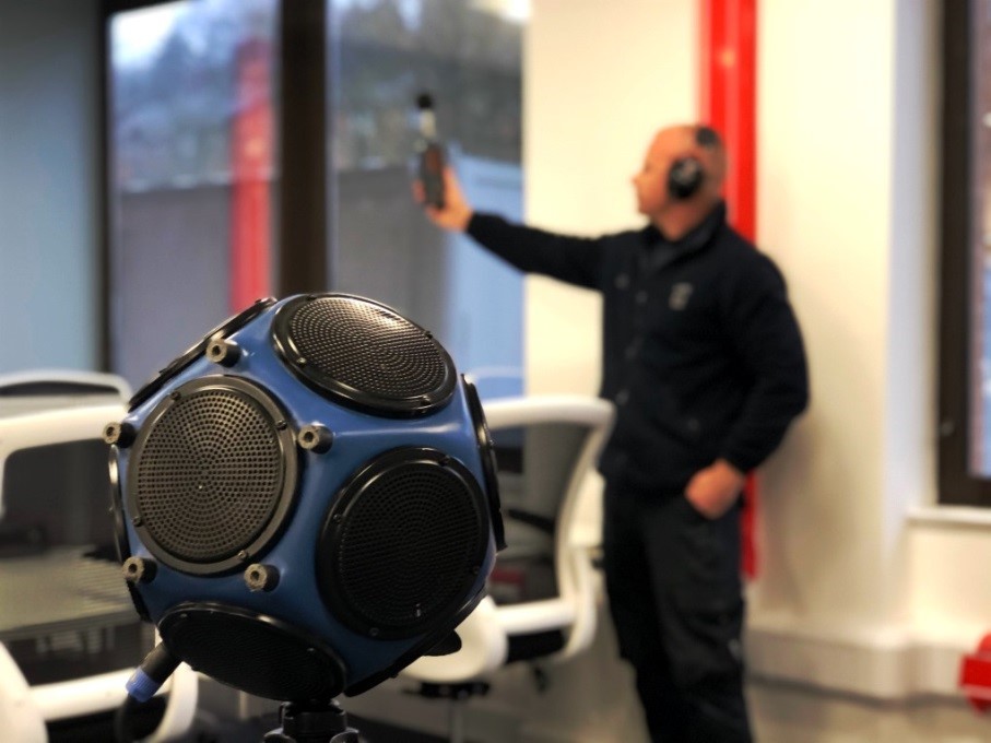
Airborne sound tests  are usually required between horizontally and vertically separated pairs of rooms. The sound tests are undertaken by using a sound source, amplifier and loudspeaker to generate a high noise level in one room (the source room). Noise measurements are then taken in both the source and receiver rooms using a prescribed number of source and microphone positions. The background levels in the receiver room are measured and the reverberation time in the receiver room is also measured. From the results, the airborne sound insulation (DnT,w + Ctr) is calculated and compared to the requirements of Approved Document E. For new build projects you are required to achieve 45dB for airborne sound testing through walls and floors and 62dB for Impact sound testing for floors. For refurbishment projects this changes to 43dB for airborne and 64dB for impact.

Impact Sound Tests
For vertically separated rooms, an Impact sound test may also be required. This sound test is undertaken using a “tapping machine”, (as above) which drops a series of weights onto the floor of the upper room. The noise level in the lower (receiver) room is measured for a prescribed number of source and microphone locations. The background levels in the receiver room are measured and the reverberation time in the receiver room is also measured. From the results, the impact sound insulation (L’nT,w) is calculated and compared to the requirements of Approved Document E.

Airborne Sound Testing of Building Facades
For the sound testing of external facades we place the loudspeaker outside  the  building  at a distance of 5m from the facade with  the  angle  of  sound incidence  equal  to  45° ± 5°  and  such  that  the  real  traffic  noise  impact  is simulated  the  best  possible  way.  The speaker and amplifier are used to generate a steady random noise signal via the loudspeaker source. The sound pressure levels are then measured at 2m in front of the facade plane and 1.5m above the ground.

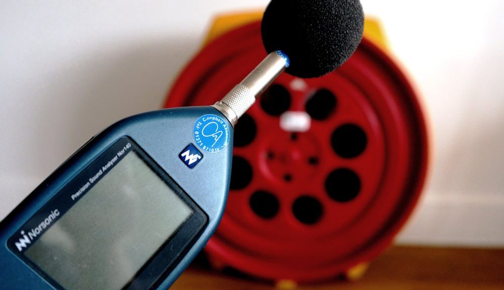
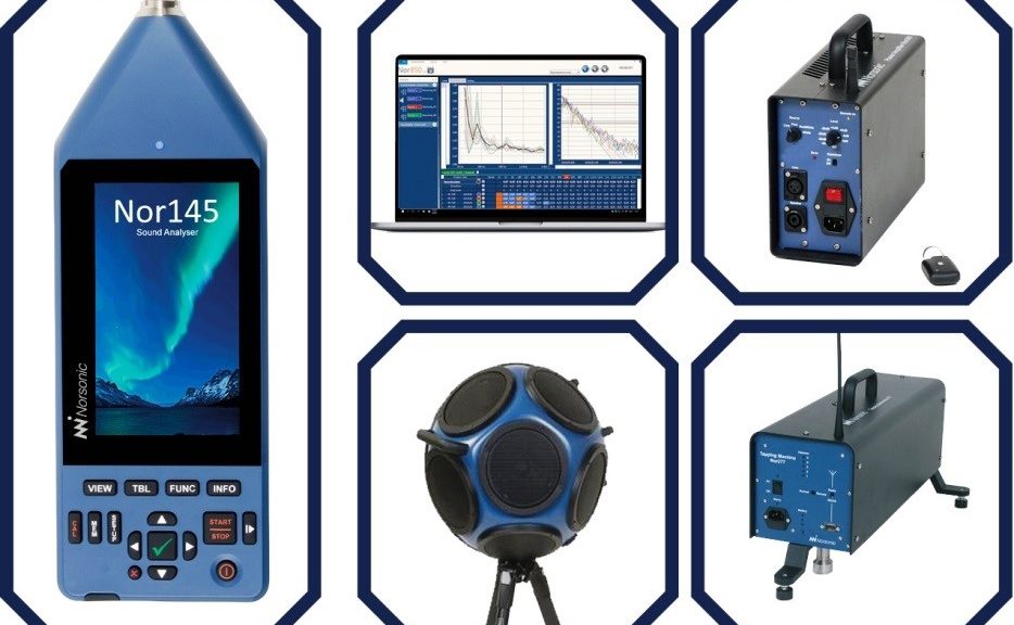
All APT’s test engineers carry the latest Norsonic sound testing equipment, which are class one rating. All of our sound testing is completed to a strict quality controlled standard. We provide full ISO & UKAS complaint sound testing.

If you would like more information in regards to the Different Types of Sound Testing please contact us 01525 303905 or visit the APT Sound Testing website today.

Types of Sound Insulation Testing

Types of Sound Insulation Testing

Types of Sound Insulation Testing

There are two types of sound insulation testing, Airborne and Impact. As the two types of testing are quite different here is a quick article explaining both types.

Airborne Sound Testing

Airborne sound testing is undertaken to walls & floors. Firstly a controlled noise is generated by an amplifier and loudspeaker across a broad range of frequencies. The generated noise is very loud and is often in excess of 100dB. Initial measurements are taken using a class 1 sound level meter within the ‘source room’ followed by further measurements in the ‘receiver room’ on the other side of the wall or floor under investigation. The source room speaker position is then changed and the measurements repeated either side of the partition under test.

two types of Sound Insulation Testing

Thereafter background noise measurements are made using a class 1 sound level meter in the receiving room and are used to apply appropriate corrections for external sound such as traffic noise. Similarly the reverberation time (the time taken for sound to decay by 60dB) is measured within the receiving room using the sound source and a sound level meter to determine the corrections that must be applied to account for the characteristics and absorptiveness of the room.

 The difference in the two airborne noise levels (for walls and floors), corrected for background and reverberation characteristics determines the airborne sound insulation performance of the wall, or floor. A greater airborne noise difference between the source room and the receiver room determines a higher airborne sound insulation performance.

The time taken to undertake sound testing varies from project to project as no site is exactly the same. Taking into account standard site conditions a set of tests on houses -two airborne walls will take one to two hours. A six pack of tests on flats – 2 airborne wall tests will usually take between one and two hours, although this is dependent on our engineers having full free uninterrupted access between all the units/rooms under investigation.

Impact Sound Insulation Testing

Impact sound transmission testing is undertaken to floors only. This test is different; a calibrated Norsonic ‘tapping machine’ which comprises of five ‘hammers’ driven up and down by a cam and electric motor is used to “tap” the floor surface by applying a known force on the floor structure. The machine is placed in several pre-determined positions. The resulting noise is measured in the dwelling below, using a sound level meter.

Thereafter, background noise measurements are made using a class 1 sound level meter in the receiving room and are used to apply appropriate corrections for external sound such as traffic noise. Similarly the reverberation time (the time taken for sound to decay by 60dB) is measured within the receiving room using the sound source and a sound level meter to determine the corrections that must be applied to allow for the characteristics and absorptiveness of the room.

The measured noise levels in the receiving room are corrected for background and reverberation characteristics determine the impact sound insulation performance of the floor. For the impact noise the lower the measured level, the better the performance as less sound is being transmitted into the dwelling below.

The time taken to undertake sound testing varies from project to project as no site is exactly the same. Impact testing is usually undertaken as part for a 6 pack test, consisting of 2 airborne walls, 2 airborne floor and 2 impact sound tests. A standard 6 pack test will usually take between two and three hours, although this is dependent on our engineers having full free uninterrupted access between all the units/rooms under investigation.

If you require sound insulation testing, and/or acoustic design advice then please contact us now at info@aptsoundtesting.co.uk  or phone me (Darren) directly on 07775623464.

Passing Your Air Tightness Test

Passing Your Air Tightness Test

Top Tips for Passing Your Air Tightness Test

APT Sound Testing has carried out thousands of air tightness tests on residential and commercial buildings. Over the last 12 years, we leaned quite a few things on how to seal buildings to pass air tightness testing to achieve building control sign-off. To try and help clients prepare their buildings, we have collated our top 10 tips to pass your air testing. :

1. Design and apply an air tightness strategy from the start of the project.

Once the design air permeability rate has been established, sit down with the design team and subcontractor trades to ensure they know the importance of designing and constructing the building to be air tight.

The air tightness line needs to be established as early as possible. This can be as easy as drawing a red line through all the elements that separate heated and unheated elements – such as plant rooms or external store rooms. Also, it is also important to have an air tightness coordinator on site to check consultant details and the associated on site construction.

Passing Your Air Tightness Test

2. Onsite construction signoff sheets throughout the build

An onsite inspection regime should be put in place throughout the construction phase to ensure that the air barrier is not compromised by poor workmanship. If the building fails the air tightness test, it can lead to very expensive remedial works.

Air leakage commonly occurs due to the inner lining of the building envelope being breached during construction. One way to prevent excess air leakage paths is to use joist hangers, rather than ‘built in’ floor joists.

3. Careful sealing during the Drylining phase

In our experience dot and dab plasterboard is often a major cause of air leakage, as any missed leakage due to unfilled mortar joints in the brick or blockwork, has a potential path from behind the board to the floor slab and up behind and through the walls.

To lower the chance of air leakage on these areas or use solid lines of adhesive around all sides of the board and any cut outs for sockets and/or parge coat the masonry walls first. It is also recommended you seal at the skirting boards/floor/wall junction wherever possible.

4. Seal around service penetrations – waste and supply pipework

Ensure all service penetrations such as waste and supply pipework is sealed where it penetrates through walls and floors. Use mastic/gunned sealants on smaller gaps; on larger gaps use pre-compressed flexible expanding foam strips or plasterboard fillets.  Do not use expanding foam as it can shrinks and break away from the surrounding construction. There are flexible foams, which are tested for air tight applications which should be fit for purpose.

5. Seal around Windows and Doors

We still see large amounts of ceilings and doors which have not been adequately sealed or are not fitting properly and need to be adjusted or eased. Use suitable draught strips, seals and sealants and to ensure there are no gaps or cracks around all window/door jambs, sills and lintels and ensure that the installers have properly checked the doors and/or windows to ensure they are closing tightly against the surrounding frames.

6. Seal around Radiator Pipes and Manifolds

Also many radiator pipes penetrate the wall behind a rad, or through the floor – which are not always obvious. Manifolds from underfloor systems are often not sealed into the floor screed, which is then covered up with carpet which still results in a large air leakage path. Carefully check and seal the areas prior to finishes being applied.

7. Seal around Loft Hatches and Eaves Cupboards

With space at a premium many dwellings have rooms designed in the roof; unfortunately this can often be the main air leakage area in dwellings. Historically, we have seen a lot of air leakage through loft hatches, eaves cupboard doors and service cupboards. As the cupboards are usually unheated the door need to be sealed as well as external doors and windows.

8. Ensure light fittings are sealed.

Down lighters can be a major cause of air leakage. Seal holes around light fittings and pull cords in the ceiling, choose airtight fittings if possible, otherwise install air tight boxes over the fitting in the ceiling void”.

9. Seal around mechanical and electrical services

It is essential that water, drainage, gas pipes, boiler flues and electricity cables are fully sealed prior to the air tightness test. Historically we often find leakage in kitchens, bathrooms, and boiler cupboards due to leaky services.

10. Kitchens and Bathrooms the main air leakage culprits

The main areas of air leakage in most new dwellings are usually within kitchens and bathrooms. Kitchens should be finished, with all mechanical and electrical service penetrations completely sealed as well as sealing to the wall/floor junction – there is not usually skirting board installed behind kitchen units as they can’t be seen once the kitchen units are in place. All appliances should be installed and all service boxing such as SVP drops fully sealed at the wall/floor junction. All extractors are fully fitted.

Bathrooms should be carefully checked and sealed around all SVP and waste pipe work. All bathroom fittings should installed and fully complete. Bathrooms often suffer with excess air leakage due leaky bath panels and waste pipe work, also the wall/floor junction is usually unsealed. You should ensure air leakage paths are fully sealed before fitting bath panels, shower bases. All boxing to vanity unit and extractors should also be sealed. For more tips on air leakage paths, see our air tightness checklist

11. Apply all temporary seals before we get to site:

If you seal all the temporary seals before we get to site it can help to expedite the test, to allow for comprehensive smoke testing in the event of a test failure.

Official guidance has set firm guidelines around what can and can’t be temporarily sealed when it comes to air tightness testing. The main contractor has the responsibility to put temporary seals in place in line with the guidelines published by ATTMA. Temporary seals can be achieved simply by using low tack masking tape as not to damage the surrounding finishes.

The allowed temporary seals are:

  • Chimney flues
  • Mechanical ventilation systems such as kitchen and bathroom extractor fans
  • Trickle vents
  • Air conditioning grilles
  • Passive ventilation such as air bricks, passive stacks and sub floor ventilation systems

12. Don’t undertake the Air Tightness Test too early

In our experience a large amount of air tightness tests failures are due to us being called in too early.

This can be a very costly mistake, which may result in re-tests, as well as the wasted man hours for the clients sealing teams as well as penalties imposed for delayed handovers. Our air tightness checklist helps our clients to check that their project is fully prepared to undertake the air tightness test.

Contact us now

If you would like more information on how to prepare your building to pass an air tightness test please visit our website at www.aptsoundtesting.co.uk or contact us at: info@aptsoundtesting.co.uk

Room Integrity Testing in London

Room Integrity Testing in London

Room Integrity Testing in London
There are literally tens of thousands of protected enclosures throughout London and the South East. With many of the banking and commercial institutions based in the capital the requirement to provide a safe environment of for critical equipment is greater than ever.

It is now a requirement of the BFPSA that all protected enclosures such as server rooms and/or data centres have valid enclosure certification – it is also a requirement of all major commercial institutions. The benefits of ensuring room integrity are widely recognised by insurers and regulatory authorities, who frequently require room integrity testing in London to prevent critical system failure on valuable assets such as server rooms and data centres.  It is also worth noting that you may negate your buildings insurance if you don’t have the valid certification.

Enclosures protected by gaseous fire suppression system -such as server rooms should be tested for air-tightness upon commissioning of the system and annually thereafter. This is critical to ensure that the system will work effectively when activated; too much air-leakage will result in the concentration of the fire suppressant agent falling too quickly resulting in rapid fire spread as shown in the image below.

For most extinguishing system types, a retention time of ten minutes is the minimum period the suppressant agents is required to be retained for within the enclosure. NFPA 2001, Standard on Clean Agent Fire Extinguishing Systems, requires that a minimum concentration of 85% of the adjusted minimum design concentration be held at the highest level of combustibles for a minimum period of 10 minutes. This is usually long enough to prevent re-ignition for most deep-seated fires and should provide adequate time for the emergency services to attend and prevent the fire taking hold.

Unfortunately, in the relevant ISO standard BS EN15004if you don’t have valid room integrity certification you may negate your buildings insurance in the event of a fire. In all instances the integrity certification should always be attached to the front of the protected enclosure/s to show it has valid certification and to clearly show the dates of the next test. The certification also has other useful information that should be adhered to at all times. If you don’t have integrity test certification fixed to the front of the enclosure, then the chances are that your enclosure may not have valid certification.

Within the In many cases the stakeholder may not be aware that any modifications have been undertaken to the room’s envelope as this may further reduce the integrity of the enclosure envelope.  That is why it’s always best to plan any works within protected enclosures so that everyone’s aware of the importance of maintaining the integrity of the enclosure envelope and the requirement for a fresh integrity test after any modifications have taken place.

Smoke Testing to Find Air Leakage Paths

APT’s highly trained and experienced Enclosure Testing Engineers will be able to locate the problem areas and identify where air is leaking out of the building by walking around the test enclosure with a localised smoke puffer – as shown in the image below)  checking the most common problem areas first.

By combining our door fan blower equipment and a small smoke puffer we can quickly locate any penetrations in in the enclosure envelope as the smoke is more visible. Smoke leaking from the enclosure can be easily seen and photographed to provide a record of any external leakage paths.
Pressurised smoke tests are ideal for identifying both generic and torturous areas of air leakage. Crucial remedial sealing work should then be undertaken to reduce the leakage from the enclosure. The sealing works may include:

•             Sealing all holes, cracks or penetrations

•             Pipe chases and cable trays to be sealed

•             Walls to be caulked around the inside perimeter

•             Sealing of porous block walls

•             Addition of drop seals, weather stripping around jambs

•             Sealing of windows/glazed sections to the area

One of the advantages of the sealing works being conducted whilst a test fan kit is in place, is that it can be seen if the works being conducted are effective via ongoing smoke testing and sealing works. Once the appropriate remedial work has been undertaken the enclosure should be retested to confirm the acceptable retention time as been achieved – usually 10 minutes.

Air Pressure Testing provides the necessary Room Integrity Testing & air tightness testing in London to the required NFPA 2001 or ISO 14520 methodologies. We have undertaken hundreds of enclosure integrity tests around the UK and Europe.

As part of our service, we can also arrange an annual test plan and remind you when the enclosure test/s are required to make sure your building’s insurance is not at risk. If you require room integrity testing in London, please call: 07775 623464 or visit the APT Sound Testing website today.

Room Integrity Testing Terminology

Room Integrity Testing Terminology

Room Integrity Testing Terminology

A gaseous fire suppression system is a highly effective method of protecting your server rooms etc. from fire. To ensure it works properly, it is important that room integrity testing is carried out when the system is first installed and thereafter at least once a year to ensure the protected area remains adequately sealed; unfortunately, this is often overlooked by the building management.

Room integrity testing checks whether the server room or enclosure – where the fire suppression system has been installed, is adequately sealed.

When undertaking the integrity testing of a new system the company tasked with undertaking the works requires quite a lot of information, which the client often struggles to answer. To try and help with this we have tried to explain the differences between a Descending Interface, Continual Mixing and Extended Discharge.

What is a Descending Interface?

The fire retardant agent is discharged from the ceiling –highest point) into the protected enclosure. An ‘interface’ with a constant concentration – known as the Initial Concentration) descends from the discharge level as gas leaves escapes from the enclosure via air leakage paths. The time it takes for this ‘interface’ to reach the minimum protected height such as the top of the server racks is defined as the Hold time. The time retention time for a Room Integrity Test Pass is usually set at 10 minutes.

What is Continual Mixing?

The suppressant Agent is discharged at near-ceiling level into the enclosure, thereafter fans circulate gas throughout the room, resulting in a uniform agent concentration. This concentration begins at initial concentration and lowers until it eventually reaches a specified minimum concentration. The time it takes for the initial concentration to reach the minimum concentration is defined as the hold time.

What is an Extended Discharge?

Typically extended discharges consist of an initial discharge for 10 to 60 seconds to get the concentration up to the design concentration. Then the extended discharge will continue at a lesser rate. The intention is for the extended discharge to replace the agent that leaks out of the room. It is assumed that the extended discharge will create enough turbulence to create a continual mixing situation throughout the extended discharge period.

We hope the above information has helped you.

If you would like some more information on our Room Integrity Testing services please call 01525 303905 or for more information please visit us at the APT Sound Testing website.